1. What Exactly Is a Round Baler and How Does It Work?
A round baler is a tractor-pulled agricultural machine designed to collect cut, dried, or standing crop material — most commonly hay, straw, rice straw, corn stalks, and soybean residue — and compress it into tight, cylindrical bales that can be wrapped in net or twine for long-term storage and transport. Unlike square balers, which form rectangular blocks, the round baler machine continuously rotates material inside a compression chamber, building up concentric layers until the target bale diameter is reached. This rolling process produces a bale whose outer shell naturally sheds water, making it well suited to outdoor storage without additional covering.
The round baler is one of the most mechanically versatile implements in modern livestock farming. Its ability to handle a wide range of crop types — from fine grasses cut for horse hay to heavy, moisture-laden silage grass — relies on a tightly coordinated interaction between the PTO (power take-off) shaft from the tractor, the internal gearbox, a chain-and-sprocket drive train, and critically, a hydraulic system that orchestrates every controlled movement the machine makes. Without pressurised hydraulic fluid flowing through a correctly designed round baler hydraulic circuit, through correctly sized lines and valves, the baler could not open its rear gate to eject a completed bale, could not apply consistent net-wrap tension, and could not adjust the round baler pickup height automatically in response to terrain changes.
In Korea, round baler adoption by livestock farmers has grown substantially as the government’s Rural Development Administration (농촌진흥청) has promoted mechanised forage harvesting to support the beef cattle (한우) and dairy sectors. The ability of the round baler to quickly bale large volumes of ryegrass and Italian ryegrass — the dominant forage crops in Korean paddies after rice harvest — has made the round hay baler an essential piece of kit on farms across Gyeonggi, Chungnam, and Jeonbuk provinces. Understanding how the hydraulic system powers each function inside that machine is not just academic; it directly affects field productivity, maintenance cost, and the service life of every moving part.
2. How the Hydraulic System Is Structured Inside a Round Baler
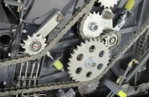
At the most fundamental level, the round baler’s hydraulic system is a closed-loop pressure circuit that borrows its power source from the tractor’s own hydraulic pump via one or two external hydraulic couplers — commonly referred to as remotes or SCV (selective control valve) outlets. The machine receives pressurised oil (typically at 180–220 bar working pressure) from the tractor and routes it through an internal manifold to each actuator. When no function is active, a return line carries the low-pressure oil back to the tractor’s reservoir, keeping the circuit in a standby condition.
Inside the baler, the hydraulic circuit branches into several parallel sub-circuits, each serving a distinct actuator. The largest and most mechanically demanding is the rear gate opening cylinder — a double-acting hydraulic ram that must exert enough force to swing open the upper half of the baler body, which in a full-size machine such as the 9YG-2.24D series weighs several hundred kilograms and holds a completed bale pressing against it with considerable force. A second sub-circuit serves the net-wrap tensioner, which may use a smaller hydraulic motor or a pilot-pressure-controlled brake clutch to feed netting material at a controlled rate. A third branch typically handles the pickup reel height adjustment, using a pair of small single-acting cylinders that float in response to ground contour, ensuring the spring-tine pickup fingers skim the stubble without digging in. More advanced models integrate a density control valve into the hydraulic manifold, allowing real-time adjustment of baling pressure in response to sensor feedback about crop throughput.
The hose routing on a well-engineered baler follows strict minimum bend-radius rules. H-type sleeve fittings — such as the H-type ferrule connectors used in the 9YG-2.24D S9000 Classic series — create a leak-resistant seal rated for the elevated pressure cycles the system repeatedly undergoes during a full working day. Each connection point is also a potential contamination entry point, which is why closed dust-cap fittings on the tractor coupler end are standard practice in quality baler design.
| Sub-Circuit | Actuator Type | Typical Working Pressure | Function |
|---|---|---|---|
| Rear Gate Opening | Double-acting cylinder | 160–200 bar | Opens / closes the rear half of the bale chamber to eject completed bale |
| Gate Cushion / Buffer | Cushion cylinder | Low-pressure damping | Absorbs shock when gate closes, protecting structural welds |
| Pickup Height Float | Single-acting cylinders (pair) | 60–100 bar (float mode) | Raises / lowers spring-tine pickup reel to follow ground contour |
| Density / Bale Pressure Control | Pressure-relief valve / proportional valve | Adjustable 80–180 bar | Regulates compression roller tension via sensor feedback |
| Net-Wrap Feed | Hydraulic brake clutch or small motor | 30–80 bar | Controls net tension and wrap initiation / termination sequence |
3. Action Modes: How Each Core Function Is Hydraulically Driven
3.1 Crop Pickup and Feeding
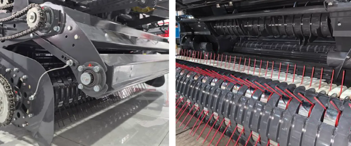
The spring-tine pickup reel of a round baler lifts windrow material off the ground and throws it backwards through a feed roller system into the compression chamber. Although the reel itself is mechanically driven by the PTO chain train, its height relative to the ground is managed entirely by hydraulics. In the “float” position, both support cylinders are connected to a low-pressure accumulator, allowing the pickup to ride up over soil mounds, stones, or furrows without operator input. This is essential on the varied paddock terrain common across Korean farmland, where post-harvest rice fields are often uneven and wet. When the operator wants to raise the pickup for road transport, a single lever command switches the valve to active extension, lifting the pickup fully. The hydraulic float function is one of the most important ergonomic features on a modern round baler machine, reducing both crop loss and daily operator fatigue significantly compared to older manual-tension designs. Many farmers comparing a round baler to a fixed-chamber design specifically cite this auto-float hydraulic pickup as a decisive factor in their equipment selection.
3.2 Compression Chamber Rolling Action
Inside the compression chamber of a drum-roller round baler (the design used across all 9YG series models), 16 to 18 fixed steel rollers are arranged in a D-shaped arc around the forming zone. Power for the rollers comes through the mechanical drive train — a combination of chains and sprockets driven from the gearbox — not directly from hydraulics. However, the hydraulic system is deeply involved in controlling the effective compression force applied. As the bale grows, the outer rollers must collectively maintain a defined inward pressure against the bale surface. The density-control sub-circuit continuously adjusts this resistance. A pressure sensor monitors the load on the star-wheel bale diameter measuring device; when the bale reaches its target size (for example, 1300 mm diameter in the 9YG-2.24D), the hydraulic control triggers the wrapping cycle. This closed-loop pressure regulation is what allows bale density to be set between 100 and 200 kg/m³ depending on the crop type and moisture content, giving operators precise control over storage volume and fermentation characteristics.
3.3 Net Wrapping
Once the bale diameter sensor signals completion, the hydraulic system switches from baling mode to wrapping mode. A solenoid valve redirects a portion of the hydraulic flow to the wrapping mechanism. In most configurations this is a hydraulic-tensioned brake that controls the unwinding resistance on the net roll, ensuring the netting is pulled snugly against the spinning bale surface rather than falling loose. The number of wrapping passes — typically 2 to 3 full rotations of the bale — is timed electronically and then the hydraulic circuit commands the cutting mechanism. Well-designed systems include a cushion valve that prevents sharp pressure spikes during the cutting stroke, which would otherwise cause hose fatigue at the crimp fittings. The net wrapping sub-circuit typically operates at relatively low flow rates compared to the gate cylinder, which means it can share the tractor’s hydraulic circuit with other functions without causing flow competition issues.
3.4 Bale Ejection
Bale ejection is the most hydraulically demanding single event in the round baler baling cycle. The operator commands the rear gate to open, and the main ejection cylinder — a large-bore double-acting ram — must exert enough force to swing open a gate loaded with a fully formed, densely compressed bale that may weigh anywhere from 200 to 500 kg depending on crop type. On the 9YG-2.24D S9000 series, the hydraulic system uses H-type ferrule connectors rated for elevated working pressure, which increases the speed at which the gate reaches full open and reduces the per-cycle hydraulic fatigue on the hose joints. Once the bale rolls free, the gate closes under hydraulic command, and a cushion cylinder on the rear hinge absorbs the closing impact, preventing the chassis welds from suffering repetitive shock loads over thousands of cycles per season. This buffer cylinder is one of the engineering details that extends machine working life substantially compared to spring-return gate designs.
4. Manufacturing Structure and Component Architecture
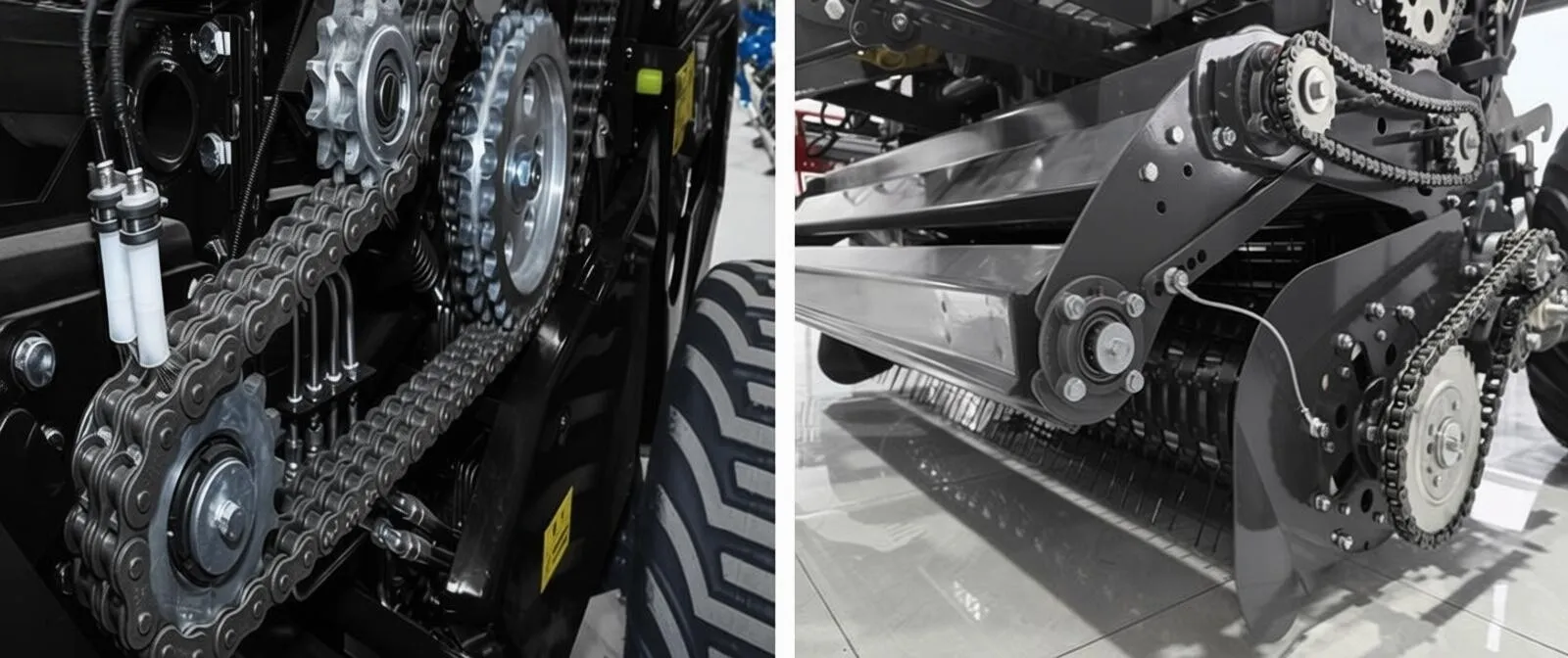
The structural integrity of a round baler is what ultimately determines whether its hydraulic system can function reliably cycle after cycle across a full harvest season. Every round baler frame must withstand the combined forces of crop intake, bale compression, and the dynamic shock loads generated when traversing field headlands at working speed. The main chassis — typically laser-cut from high-strength structural steel plate — forms the rigid backbone to which all hydraulic actuators anchor. If the chassis flexes excessively under load, cylinder mounting points shift out of alignment and hydraulic hose routing can be strained beyond its design tolerance. This is why quality manufacturing begins with precise CNC laser cutting of all structural members before any welding takes place.
The compression chamber itself is assembled from the roller mounting plates, the front and rear gate half-shells, and the sidewall frames. Each hydraulic cylinder mount on the gate is reinforced with gusseted flanges that distribute the cylinder’s reaction force across a wide area of the gate structure rather than concentrating it at a single bolted boss. The rear gate hinges use hardened steel pivot pins running in sealed spherical bearings that are pre-loaded with grease at assembly and can be re-greased through zerks during maintenance. This bearing arrangement ensures that the angular geometry between the gate and the main frame remains constant throughout the gate’s 110–130° opening arc, which is critical for maintaining hose travel within the designed envelope and preventing kinking.
On the transmission side, the dual gearbox architecture used in several 9YG-2.24D variants allows the gearbox to rotate 90 degrees left or right relative to the tractor hitch axis. This substantially reduces the turning radius penalty associated with a towed implement, and the gearbox’s rigid connection to the drawbar means the drive shaft never experiences the torsional shock loads that a purely flexible PTO arrangement would produce on uneven ground. From a hydraulic standpoint, this stability also benefits the hydraulic hoses routed along the tongue, since they flex only within a predictable angular range during tight turns rather than being whipped randomly.
| Structural Component | Manufacturing Method | Hydraulic Relevance |
|---|---|---|
| Main Chassis Frame | CNC laser-cut structural steel, MIG welded | Provides rigid anchor for all cylinder mount points |
| Rear Gate Half-Shell | Press-formed plate, gusseted hinge flanges | Carries ejection cylinder and cushion cylinder mounts |
| Roller Mounting Plates | Precision-bored, heat-treated steel | Maintains geometric alignment under hydraulic compression load |
| Hydraulic Manifold Block | Machined ductile iron or aluminium alloy | Routes flow to all sub-circuits via integrated valve bores |
| Hose Routing Brackets | Stamped and powder-coated mild steel | Maintains minimum bend radius, prevents abrasion fatigue |
5. Material Systems and Steel Selection
The hydraulic components inside a round baler operate in one of the harshest environments in agricultural machinery — constant vibration, cyclical pressure loading, exposure to dust, crop moisture, and wide temperature swings from early morning dew to mid-afternoon summer heat. Every round baler hydraulic component must be specified not just for its steady-state working conditions but for the peak transient loads that occur during the most demanding moments in the baling cycle. Selecting the correct material for each component in the hydraulic circuit is therefore not a secondary engineering consideration; it is foundational to long-term reliability.
Hydraulic cylinders are the most critical single components in the circuit from a materials perspective. The barrel bore of a quality cylinder is honed to a surface roughness of Ra 0.4 µm or better to ensure the piston seal maintains a consistent oil film without excessive leakage. The cylinder barrel itself is typically drawn from seamless cold-rolled steel tube with a minimum yield strength of 500 MPa, which provides adequate safety margin against the burst pressure encountered when the gate opens against a fully loaded bale. The piston rod is hard chrome-plated over a low-alloy steel core to a minimum hardness of 800 HV (Vickers), giving it excellent resistance to corrosion and mechanical scraping from airborne grit. Some premium designs use induction-hardened rods with ceramic-composite coatings, which extend the service interval between seal replacements significantly.
Hydraulic hoses on a round baler must withstand both the static working pressure of the main circuit and the pressure spikes (water hammer) that occur each time a valve closes sharply. SAE 100R2AT two-wire braid hose is the industry standard for the high-pressure lines connecting to the gate cylinder, rated to 400 bar burst pressure with a 4:1 safety factor on a 100 bar working line. The outer rubber sheath incorporates an anti-abrasion formulation that resists the constant rub against chaff and crop material. Low-pressure return lines and drain lines use single-wire braid SAE 100R1AT hose, which is more flexible and better suited to the wider bend radius paths of the pickup float circuit.
Cylinder Barrel
Seamless cold-rolled steel, min. yield 500 MPa. Honed bore Ra ≤0.4 µm for optimal piston seal life.
Piston Rod
Hard chrome-plated low-alloy steel core, 800 HV hardness. Resists corrosion and grit abrasion in field conditions.
High-Pressure Hose
SAE 100R2AT two-wire braid, 400 bar burst rated. Anti-abrasion outer sheath for crop-contact areas.
Manifold Block
Ductile iron (GGG50) or 6061-T6 aluminium alloy. Integral valve bores reduce leak-point count versus ported fittings.
6. The Gearbox’s Role in the Hydraulic Chain
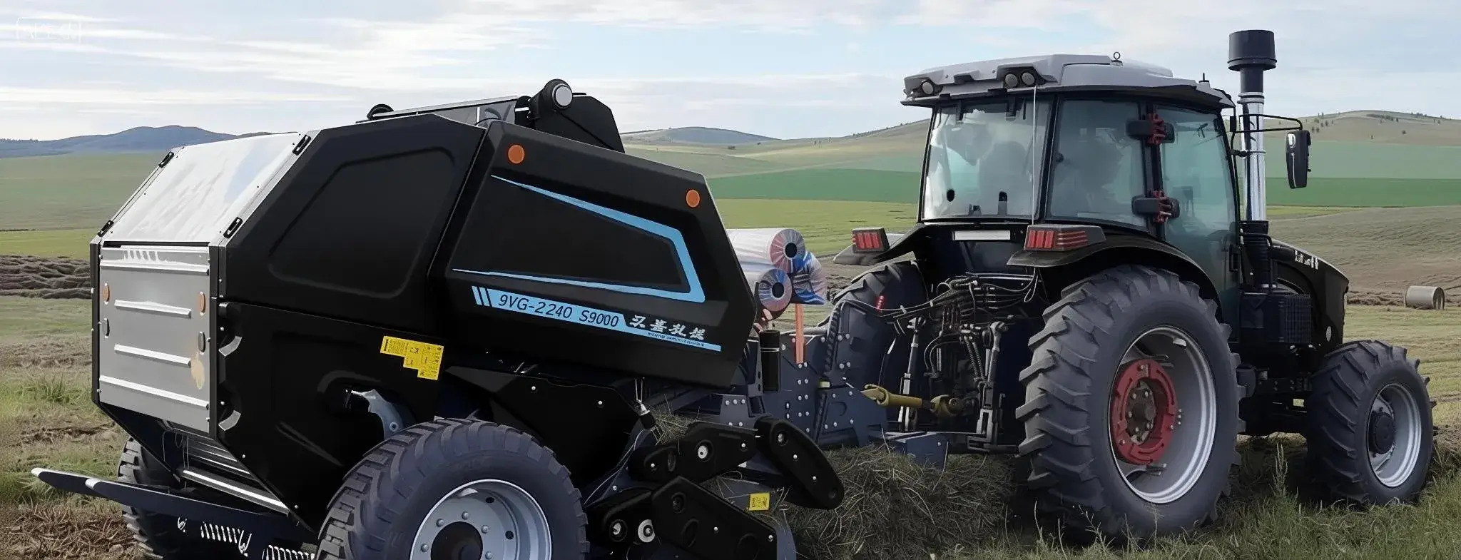
A round baler gearbox does not directly generate hydraulic pressure — that job belongs to the tractor — but it is architecturally inseparable from the hydraulic system’s performance. Understanding the round baler’s drivetrain helps explain why certain gearbox configurations protect hydraulic performance more effectively than others. The gearbox receives PTO input at 720 r/min (the standard operating speed for the 9YG round baler series) and distributes this rotational energy to the compression rollers, the pickup reel, and the feed auger or roller. The efficiency with which it does this directly determines how much residual PTO torque is available to drive the tractor’s hydraulic pump. On a heavily loaded round baler working at 40–100 bales per hour in dense Korean ryegrass, the mechanical power absorbed by the baler’s own drive train can be 30–50 kW out of a tractor with a total PTO output of 55–100 kW. If the gearbox is inefficient, the hydraulic pump receives less consistent oil pressure, which translates directly into slower gate opening, reduced density control authority, and erratic net-wrap tension.
The dual gearbox design employed in the 9YG-2.24D S9000 round baler series takes this a step further by allowing the entire gearbox-and-tongue assembly to rotate 90 degrees laterally. This means the baler can negotiate sharp field headlands without requiring the tractor to make wide arcs, and — importantly for the hydraulic circuit — the PTO drive angle stays within a safe operating range throughout the turn. A universal joint operating at excessive angle generates cyclical velocity variation that sends pressure pulses through the gearbox and into the transmission chain, potentially causing cavitation in the hydraulic pump if the pulses are severe enough. The self-aligning dual-gearbox design largely eliminates this risk by keeping the PTO shaft angle close to zero even during tight manoeuvres.
The 9YG-2.24D Classic round baler version of this design also features a dual-sided sprocket drive for the rear bale chamber. This spreads the drive torque across both sides of the roller assembly, reducing the peak tensile load on each individual chain link and the associated bending moment on the roller shaft journals. From a hydraulic standpoint, this means the compression force generated by the hydraulic density control circuit is transmitted to the bale more evenly, reducing the tendency for bales to be denser on one side than the other — a defect that is particularly noticeable in Korean silage bales where even density is critical for consistent fermentation quality.
7. Sensor-Controlled Bale Density: How It Works
All models in the 9YG round baler series use sensor-controlled bale density management rather than fixed mechanical pre-tension. This is worth explaining in depth because it is one of the most practical advantages a hydraulically sophisticated round baler offers over older designs, and it directly addresses the crop variability challenges Korean farmers face when baling Italian ryegrass at different moisture levels across the same paddock. Farmers shopping for a round hay baler specifically ask about density control capability more than almost any other feature.
The round baler sensor system works by measuring bale diameter through a rotary position sensor connected to a star-wheel measuring arm that rides against the growing bale’s outer surface. As the bale grows from zero to its target diameter — 1300 mm in the case of the 9YG-2.24D, or 1100 mm for the 9YG-1.0 — the electronic controller interprets the star-wheel position and sends a signal to a solenoid valve in the hydraulic density control circuit. This valve modulates the back-pressure on the chamber-exit side of the compression cylinder hydraulic line, effectively increasing or decreasing the force with which the rollers press inward against the bale. In wet crop conditions, where excessive compression would squeeze out too much moisture and collapse the cellular structure of the forage, the target pressure is set lower. In dry, low-density straw, higher pressure compensates for the crop’s natural tendency to spring back after compression. The result is bales with consistent density in the 100–200 kg/m³ range across a wide variety of crop conditions.
The practical consequence for Korean beef and dairy farmers evaluating which round baler model to buy is significant. Consistent bale weight means consistent load counts per transport trip, which simplifies logistics planning. Even density means uniform silage fermentation quality, which has a measurable impact on feed intake and daily gain in beef cattle operations. And the automatic nature of the sensor control means that a single operator can work a full shift without needing to stop and re-adjust the baler as crop conditions change — a crucial advantage during the narrow harvesting windows dictated by Korean weather patterns.
8. Round Baler Product Lineup and Specifications
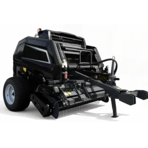
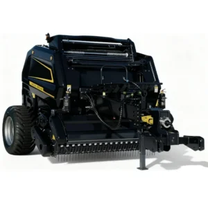
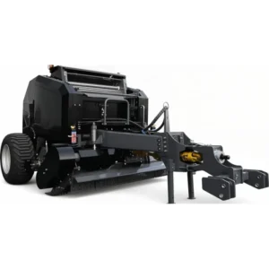
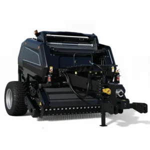
The following round baler models — covering mini round baler and full-size round baler configurations — represent the full range of available configurations, from compact small round baler options suited to 48 kW tractors up to heavy-duty 100 kW models for large-scale commercial forage operations.
9. Legal Regulations Governing Round Baler Hydraulic Systems
Agricultural machinery hydraulic systems — including those on round balers — operate in one of the most regulated equipment categories in global farming. Understanding these rules matters whether you are a round baler manufacturer seeking market access, a dealer importing round baler machines, or a farmer seeking to confirm subsidy eligibility for a new round hay baler purchase. Round baler hydraulic circuits are subject to a layered set of national and international technical regulations that govern their design, manufacturing, and operational safety. Farmers and dealers evaluating a small round baler for sale should be aware of the applicable standards in their operating country to ensure both legal compliance and insurance validity.
Korea (대한민국)
In South Korea, agricultural machinery is regulated under the Act on the Promotion of Agricultural Mechanisation (농업기계화 촉진법) administered by the Ministry of Agriculture, Food and Rural Affairs (MAFRA). All imported or domestically produced round baler and other agricultural machines offered for subsidy under the Agricultural Machinery Subsidy Programme must obtain an Agricultural Machinery Performance Test Certificate (농업기계 성능검정서). The hydraulic system on a round baler must demonstrate compliance with KS B ISO 4413 (Hydraulic Fluid Power — General Rules and Safety Requirements for Systems and Their Components). Hydraulic hose assemblies must meet KS M 6357 or the equivalent ISO standard for operating pressure ratings. Korean safety regulations additionally require clearly labelled hydraulic connection points, an operator-accessible pressure relief valve, and lockout provisions that prevent accidental rear gate activation while an operator is near the discharge zone.
European Union
Round baler machines sold in EU member states must comply with the Machinery Directive 2006/42/EC (being replaced by EU Machinery Regulation 2023/1230 from January 2027 onward). This directive requires a CE mark based on conformity with harmonised standards including EN ISO 4413 for hydraulic systems and EN ISO 11684 for safety signs on agricultural machinery. The maximum permitted hydraulic system working pressure, hose ratings, cylinder end-of-stroke cushioning, and gate locking provisions are all addressed in these standards. Operators in Germany, France, the Netherlands, and Scandinavia should also be aware of national agricultural accident prevention regulations (DGUV Vorschrift 74 in Germany, for example) that set requirements for hydraulic system inspection intervals — typically annual inspection of all hose assemblies and pressure-relief valve settings.
United States and Canada
In North America, there is no federal hydraulic machinery standard specifically for balers, but the American Society of Agricultural and Biological Engineers (ASABE) Standard ASAE S430 covers the safety requirements for tractor-powered equipment including hydraulic circuit interfaces. OSHA 29 CFR 1928 (agricultural operations safety) applies to farm workers operating round hay balers and requires that all guards over moving parts be in place during operation and that hydraulic pressure be relieved before any maintenance on the system. Canadian provinces follow similar guidelines under provincial occupational health and safety acts, with Agriculture Canada recommending annual hydraulic hose inspection and replacement after five years regardless of visible condition.
ISO International Standards
At the international level, ISO 11684 (Safety Signs) and ISO 4413 (Hydraulic Systems Safety) are the primary standards referenced by round baler manufacturers seeking to supply multiple markets with a single machine design. ISO 4413:2010 specifically addresses maximum working pressures, filter requirements (typically β10 ≥ 75 cleanliness rating for the main circuit), hose selection criteria, and contamination control procedures. ISO 11684 mandates pictographic warnings on any hydraulic component that poses a crush, injection, or scalding hazard if operated or serviced incorrectly. A round baler manufacturer holding ISO 9001 quality management certification demonstrates that its hydraulic system design and assembly processes are audited against these requirements on a regular basis.
| Region | Primary Standard / Law | Key Hydraulic Requirements |
|---|---|---|
| Korea | 농업기계화 촉진법 / KS B ISO 4413 | Performance test certificate, pressure relief valve, lockout provision |
| European Union | Machinery Directive 2006/42/EC / EN ISO 4413 | CE marking, annual hose inspection, gate locking, safety signs |
| USA | ASABE S430 / OSHA 29 CFR 1928 | Guards in place, pressure relief before maintenance |
| Canada | Provincial OHS Acts / Agriculture Canada | Annual hose inspection, 5-year replacement regardless of condition |
| Russia / CIS | GOST R 52777 / TR CU 010/2011 | EAC mark required for market access; hydraulic pressure certification |
| International | ISO 4413:2010 / ISO 11684 | Hose selection, contamination control β10≥75, pictographic warnings |
10. Hydraulic Maintenance Best Practices for Farm Operations
The hydraulic system on a round baler is relatively compact compared to a combine harvester or self-propelled forage chopper, but it operates under demanding conditions and deserves a structured maintenance routine. The round baler operates through thousands of compression cycles per season, and the most common cause of hydraulic failure in field conditions is not component fatigue but contamination — crop dust, soil particles, and water ingress that degrade the hydraulic oil, accelerate valve spool wear, and cause cylinder seal failures well before their designed service life. A well-maintained round baler hydraulic circuit can remain fully functional for 10 or more seasons without major component replacement.
At the start of each round baler season, the hydraulic oil in both the tractor’s reservoir and any baler-mounted accumulator or reservoir should be checked for milky discolouration (indicating water contamination), dark brown or black colour (indicating oxidation), or visible particulate matter. ISO cleanliness target for a round baler hydraulic circuit is typically 17/15/12 per ISO 4406, which can be verified inexpensively with a bottle sample sent to a fluid analysis laboratory. All hydraulic hose assemblies should be visually inspected for surface cracking in the outer rubber sheath, particularly at the crimp ferrule ends where fatigue cracks typically initiate first. Any hose showing cracking, kinking, or oil weeping at a fitting should be replaced immediately, not at the end of the season. Quick-disconnect coupler dust caps should be cleaned and checked for seal integrity before connecting to the tractor’s remote outlets.
Mid-season round baler maintenance should include a check of cylinder rod seals for weeping — a thin film of oil on the rod is acceptable (it lubricates the wiper seal) but visible dripping indicates seal replacement is needed. The hydraulic filter element, if the baler has an integral return-line filter, should be replaced at the interval specified by the manufacturer, typically after the first 50 hours and then annually thereafter. At round baler season end, cycle the rear gate open and close at least five times with the tractor hydraulics at normal operating temperature to flush any condensed moisture from the cylinder bores before winter storage.
Seasonal Hydraulic Maintenance Checklist
- Check hydraulic oil colour and clarity — replace if milky or dark
- Inspect all hose assemblies for surface cracking and ferrule weeping
- Clean and inspect all quick-disconnect dust caps for seal integrity
- Verify pressure-relief valve setting (compare to specification plate)
- Cycle rear gate 5× at operating temperature — note cycle time and smoothness
- Check cylinder rod seals for excess oil weeping
- Replace integral filter element (first 50 h, then annually)
- Confirm density sensor arm moves freely and sensor reads correctly
- Grease all cylinder pivot pins and gate hinge pins
11. Troubleshooting Common Hydraulic Failures in the Field
Even well-maintained hydraulic systems on round balers occasionally develop problems, and being able to diagnose the fault quickly in the field can mean the difference between a brief stop and losing an entire day’s harvest window. Round baler hydraulic faults tend to follow predictable patterns related to contamination, seal wear, or coupler issues. When a round baler gate is slow, when the round baler density sensor triggers incorrectly, or when a round baler loses hydraulic pressure mid-field, the cause is almost always traceable to one of the categories below. related to contamination, seal wear, or coupler issues rather than catastrophic internal failures. The table below covers the most frequently encountered hydraulic issues on drum-roller round balers, along with their most probable causes and first-response corrective actions.
| Symptom | Probable Cause | First-Response Action |
|---|---|---|
| Rear gate opens very slowly or incompletely | Low tractor hydraulic oil level; coupler not fully engaged; restricted return line | Check tractor oil level; re-seat couplers; inspect return hose for kink |
| Rear gate slams shut on closing | Cushion cylinder not functioning; flow-control valve clogged or bypassing | Test cushion cylinder isolation; clean or replace flow-control orifice |
| Bale density inconsistent (loose bales) | Density sensor arm not pivoting freely; pressure-relief set too low | Clean and lubricate sensor pivot; check relief valve setting vs. spec |
| Net wrap starts prematurely or won’t cut | Solenoid valve fault; hydraulic pressure to wrap brake below minimum | Check solenoid connection; verify hydraulic pressure at wrap sub-circuit port |
| Oil leak at gate cylinder rod | Rod seal worn; rod surface corroded / pitted | Replace rod seal kit; polish or replace rod if pitting depth exceeds 0.1 mm |
| Pickup reel drops unexpectedly during work | Float valve leaking; check valve in lift circuit worn | Isolate float valve; if leak confirmed, replace valve cartridge |
Frequently Asked Questions
Q1. How does the hydraulic system in a Korean farm round baler control bale density for ryegrass silage operations? +
Q2. Which round baler gearbox specification should Korean farmers look for when buying a small round baler for a 40 hp tractor? +
Q3. What are the hydraulic hose replacement intervals recommended for round balers operating in Korean summer humidity conditions? +
Q4. Where can Korean livestock farmers get a supplier quote for round baler parts including hydraulic cylinders and seal kits? +
Q5. How does the round baler hydraulic net-wrap system work differently from a twine-tie system in terms of fluid circuit complexity? +
Q6. When should a Korean beef cattle farmer replace the hydraulic seal kits on a round baler rear gate cylinder during the annual service schedule? +
Q7. What tractor hydraulic flow rate is needed to operate a round baler gate cylinder at an acceptable open-and-close speed in Korean paddy field conditions? +
Q8. How does the cushion cylinder design in a round baler’s rear gate hydraulic system prevent structural damage over thousands of baling cycles? +
Q9. Which round baler machine is best suited to corn stalk baling in Korean autumn harvest conditions, and what hydraulic setup does it use? +
Q10. How does the round baler dual gearbox affect the hydraulic hose routing and service life on hilly Korean farmland terrain? +
Editor: PXY