The chamber door — often called the tailgate — is the hinged rear assembly of a fixed-chamber round baler that opens to discharge each completed bale and closes again before the next bale begins to form. On flat, well-prepared fields, this cycle is predictable and low-stress for the mechanism. On rough pasture terrain, however, the situation is quite different. Slopes, irregular ground, concealed stones, and abrupt transitions between soft and hard footing all generate unpredictable vertical and lateral forces that transmit through the baler chassis into the tailgate hinge and latch points. Without effective damping of these forces, tailgate assemblies on round baler machines experience accelerated fatigue at the hinge welds, latch bolt wear, and hydraulic cylinder seal failure — all of which translate to mid-season breakdowns at precisely the moments when the baling window is shortest.
The hydraulic buffer cylinder is the component specifically engineered to absorb and dissipate these impact loads. Understanding how it works, what its failure signatures look like, and how to maintain it correctly is practical knowledge for any livestock farmer or forage contractor operating a round baler on challenging ground — including the highland meadows and sloped pasture parcels common across Gangwon Province and the central mountain belt of South Korea. This article covers the engineering, materials, maintenance requirements, and regulatory context relevant to this component, with specific reference to the round baler models available in the current product range.
What Is a Hydraulic Buffer Cylinder on a Round Baler?
A hydraulic buffer cylinder — sometimes referred to as a tailgate damper or chamber door cushioning cylinder — is a hydraulic actuator installed in parallel with the main tailgate lift cylinder on a round baler machine. While the main lift cylinder provides the force to open and hold the tailgate during bale discharge, the buffer cylinder provides controlled resistance during the closing phase and absorbs shock loads generated during field travel on rough terrain. On some designs, a single dual-function cylinder handles both lifting and buffering; on others, separate cylinders are used for each function.
The buffering action works through hydraulic flow restriction. When an external force acts on the closed tailgate — for example, when the baler hits a rut that causes the chassis to pitch sharply — the resulting inertial load tries to push the tailgate hinge beyond its normal static resting angle. The buffer cylinder resists this movement by throttling the hydraulic fluid displaced through an internal orifice or a pilot-operated check valve. The energy of the impact is converted to heat in the hydraulic fluid, rather than being transmitted as a mechanical stress pulse into the hinge weldment, latch hardware, and connecting frame structure. This is the same operating principle used in automotive suspension dampers and hydraulic door closers — the geometry and scale are different, but the physics are identical.
On higher-specification round baler machines, the buffer cylinder also serves as a pressure-relief safety device during bale formation. As the bale grows inside the fixed chamber, internal pressure rises progressively. If that pressure exceeds the calibrated limit before the net wrap cycle completes, a built-in relief valve in the buffer cylinder circuit allows controlled displacement of the tailgate — preventing catastrophic pressure buildup that would otherwise split the side panels or damage the chamber roller bearings. This dual safety function makes the buffer cylinder one of the most mechanically important components on any round baler destined for heavy pasture use.
Rough Pasture Terrain: What Forces Does the Baler Chamber Door Actually Face?
Korean highland grasslands — particularly in Gangwon, North Chungcheong, and South Jeolla provinces — are among the more challenging operating environments for round baler equipment in East Asia. Parcels are often sloped at 5–15 degrees, with irregular micro-topography from natural erosion, seasonal frost heave, and the compaction patterns left by livestock grazing through wet conditions. Boulders and embedded stones are common in highland meadow soils, and the transition between the field surface and access tracks frequently involves sharp grade changes that cause the baler chassis to pitch and yaw abruptly as the tractor traverses them.
Each of these terrain features generates a distinct force signature at the tailgate. A sharp vertical pitch event — the baler dropping into a depression — creates an upward inertial force on the tailgate hinge that momentarily lifts the door against its latch. A lateral yaw event — one wheel dropping while the other remains high — introduces a twisting moment across the tailgate width that tries to rack the hinge pin in its bushing. On sloped ground, the weight of a partially formed bale inside the chamber shifts toward the lower side, changing the pressure distribution across the tailgate face in ways that were not present during flat-field calibration. Over a typical baling season of 30–60 working hours on this type of ground, a round baler without effective hydraulic buffering accumulates damage at the tailgate that manifests as hinge bushing wear, latch bolt elongation, and eventually hydraulic cylinder seal leaks from repeated overextension.
The cumulative fatigue picture becomes clear when you count the individual tailgate cycles across a season. On a compact round baler producing 30 bales per hour over 50 working hours, that amounts to 1,500 close-and-open cycles. Each cycle involves at least one full compression event where the tailgate is under bale pressure and one discharge event where it opens under hydraulic power and closes under gravity-assisted cylinder return. If each cycle also includes one terrain-induced shock event — a conservative assumption on highland Korean pasture — then 1,500 high-energy impact pulses are accumulating at the hinge assembly across the season. Effective hydraulic buffering absorbs the great majority of these pulses before they reach the structural welds.
Manufacturing Structure: How the Hydraulic Buffer System Is Built
Cylinder Body and Rod Construction
The buffer cylinder body is typically a precision-bored seamless steel tube, with internal surface roughness Ra 0.4 or better to ensure consistent seal performance throughout the service life. The piston rod is ground from case-hardened steel bar — typically 40Cr or 42CrMo — to achieve a surface hardness of HRC 50–58 combined with a chrome plating thickness of 20–25 microns. The chrome layer provides the corrosion protection needed in outdoor agricultural environments while maintaining the surface smoothness required for lip seal integrity. On quality round baler buffer cylinders, the rod diameter is sized with a safety factor of at least 1.5 against Euler buckling at maximum extension, which matters particularly when the cylinder is in the extended position during bale discharge on a side slope.
The cylinder end caps — at both the rod end and the cap end — are machined from forged steel rather than cast iron. Forgings provide better impact resistance at the thread roots and clevis pin bore than castings, which can micro-crack at these stress concentration points when subjected to the repetitive shock loading typical of rough-terrain round baler operation. The clevis pin itself is a hardened alloy steel pin running in a bronze bushing, which allows controlled wear of the replaceable bushing while protecting the more expensive cylinder clevis from direct wear contact.
Internal Valve and Orifice Design
The buffering function is controlled by one or more internal hydraulic orifices — precision-drilled restriction passages that control the rate at which fluid can move through the cylinder during a shock event. On basic buffer cylinder designs, the orifice is a fixed-diameter hole drilled in the piston or end cap. On more sophisticated designs, a pilot-operated check valve is integrated into the piston, which opens freely in the controlled-extension direction but restricts flow in the impact-loading direction to a calibrated rate. This directional asymmetry means the cylinder extends quickly during normal door-opening cycles (improving cycle time) but resists rapidly in the compression direction when terrain impact loads arrive — exactly the behaviour needed for effective buffering without slowing operational throughput.
Sealing System
The seal stack in a round baler buffer cylinder typically comprises a rod wiper seal, a rod seal, and a piston seal — all manufactured from polyurethane or PTFE composite compounds rather than standard nitrile rubber. Polyurethane seals offer superior abrasion resistance on the rod surface and maintain their elastic properties over a wider temperature range than NBR, which is important on Korean highland operations where morning temperatures in early autumn can be below 5 degrees C while afternoon temperatures reach 25 degrees C. PTFE composite piston seals provide low-friction guidance for the piston while maintaining the differential pressure needed for the buffering function to work correctly.
Hinge Assembly and Frame Integration
The tailgate hinge on a round baler machine is a continuous tube-and-pin assembly spanning the full width of the chamber opening — typically 1.0 to 1.5 m for compact models and 1.5 to 2.4 m for full-size machines. The hinge tube is welded to the upper tailgate frame using full-penetration welds confirmed by visual and dimensional inspection on quality-controlled production lines. Hinge pin diameter is sized to the bale weight and field load estimates; for compact balers producing bales up to 300 kg, 40–50 mm diameter pins in phosphor-bronze bushings are typical. The buffer cylinder mounting brackets are welded to the main chassis frame at gusset-reinforced attachment points, ensuring the cylinder reaction loads distribute into the main structural members rather than concentrating at the weld toes.
Material System: Component Materials in the Hydraulic Buffer Circuit
The material choices across the hydraulic buffer cylinder and its associated circuit components directly determine service life under the high-cycle, shock-loaded conditions of rough pasture baling. The table below summarises the key materials across each sub-component, along with the specific property that makes it appropriate for this application.
| Component | Material | Key Property | Rough-Terrain Relevance |
|---|---|---|---|
| Cylinder Tube | Seamless cold-drawn steel (ST52) | ID tolerance H8; Ra 0.4 inner surface | Consistent seal contact ensures buffer function remains calibrated after repeated shock cycles |
| Piston Rod | 42CrMo alloy steel, hard chrome plated | HRC 50–58; chrome 20–25 micron | Resists lateral bending load from yaw events; chrome prevents corrosion in outdoor storage |
| End Caps | Forged 40Cr steel, machined | Tensile 900 MPa; no casting porosity | Impact shock at thread roots during pitching events absorbed without micro-cracking |
| Rod Seal | Polyurethane (PU 92 Shore A) | Wear resistant; −30 to +100 C range | Maintains seal integrity across Korean seasonal temperature extremes; resists abrasive dust ingress |
| Piston Seal | PTFE-glass composite | Low friction; pressure differential stable | Maintains orifice-controlled pressure differential during rapid loading; low stick-slip |
| Clevis Pin | Hardened 40Cr steel, in bronze bushing | HRC 45–52; sacrificial bushing design | Bushing absorbs lateral impact wear; pin protected from direct contact damage |
| Hydraulic Fluid | ISO VG 46 or VG 68 hydraulic oil | Viscosity index 100 minimum | Maintains consistent buffer orifice flow resistance across operating temperature range |
| Hinge Pin | 40–50 mm dia. alloy steel in phosphor-bronze bush | Fatigue limit 350 MPa; greasable | Sustains bale weight combined with terrain shock; regreasable bush extends service life |
One consideration specific to Korean highland conditions is hydraulic fluid selection. Operators who store their round baler outdoors through the Korean winter months — where temperatures in Gangwon Province regularly reach −15 to −20 degrees C — should confirm that their tractor hydraulic fluid and any fluid in the baler cylinder circuit is rated for low-temperature operation. Standard ISO VG 46 oil can increase viscosity significantly below −10 degrees C, which would change the orifice flow rate in the buffer cylinder and potentially allow faster tailgate movement than the design intent. Using a low-viscosity-index synthetic hydraulic fluid rated to −30 degrees C startup is a sensible precaution for highland Korean operations that may begin the baling season before temperatures have fully risen in late spring.
Recognising Buffer Cylinder Failure Before It Becomes a Breakdown
Hydraulic buffer cylinder failure on a round baler rarely happens suddenly. The most common failure mode is progressive — a slow deterioration of the rod seal allows hydraulic fluid to bypass the piston over thousands of cycles, reducing the cylinder buffering pressure and allowing the tailgate to move more freely during terrain shock events. By the time the seal has failed enough to cause visible oil weeping on the rod exterior, the buffer function has already been partially lost for some time. Understanding the early indicators of deterioration allows operators to address the issue at routine maintenance rather than during an unplanned mid-season stoppage.
A metallic clunk from the rear of the baler when traversing ruts or road cambers indicates that the tailgate is momentarily displacing beyond its normal resting angle, then returning — a signature of reduced buffer resistance. This is typically the first field symptom of buffer cylinder seal wear.
A film of hydraulic oil visible on the piston rod surface, particularly after the baler has been stationary overnight, indicates rod seal bypass. At this stage the buffer function is compromised; seal replacement should be scheduled for the next available opportunity, typically end-of-day rather than mid-field.
A failed buffer cylinder allows the tailgate to flex slightly under asymmetric bale pressure on side slopes, producing bales with slight flat spots or off-centre cross-sections. This is a less obvious symptom but is particularly noticeable when baling on the consistent 5–10 degree slopes common in Korean highland meadow parcels.
At the end of season inspection, if the hinge pin shows measurable lateral play in its bushing despite being correctly greased during the season, this is a strong indicator that shock loads have been reaching the hinge without adequate buffering. Replace both the buffer cylinder seals and the hinge bushing before the next season.
Maintenance Schedule for the Hydraulic Buffer System on a Round Baler
Maintaining the buffer cylinder correctly extends its service life well beyond the typical three-to-five-year replacement cycle that operators on rough terrain often experience when maintenance is reactive rather than preventive. The schedule below is based on the operating conditions of compact round baler machines working 30–60 hours per season on Korean highland grassland, where terrain loading is moderate to high and humidity levels are sufficient to accelerate surface corrosion on unprotected rod surfaces.
| Interval | Task | What to Check / Do | Risk if Skipped |
|---|---|---|---|
| Before first field session each season | Full cylinder and hinge inspection | Check rod for pitting or scoring; confirm no oil film on rod; cycle tailgate 3–5 times under full hydraulic pressure | Undetected seal wear fails during first heavy baling session |
| Every 8 working hours | Grease hinge pin bushings | Apply NLGI Grade 2 lithium-complex grease until fresh grease appears at bushing ends; wipe off excess | Dry bushing accelerates hinge pin wear; concentrates shock load at buffer cylinder clevis |
| After every 50 bales on rough terrain | Visual rod check | Wipe piston rod with clean cloth; any oil transfer indicates early seal bypass | Missed early failure leads to accelerated hinge damage before end-of-day inspection |
| End of each day during baling season | Check clevis pin retention and rod condition | Confirm clevis pins are retained by split pins or locking washers; check rod surface for new scoring from grit | Lost clevis pin causes immediate tailgate loss of control during next discharge cycle |
| End of season | Full disassembly inspection | Measure hinge pin lateral play; check cylinder mount welds; drain and flush hydraulic circuit if fluid is discoloured | Concealed hinge wear or cracked mount weld discovered during next season under load |
One practice worth emphasising for Korean highland operators: coat the piston rod with a thin film of clean hydraulic oil before storing the baler over the winter months. This simple step prevents surface rust forming on the chrome layer in the rod-exposed area during the 5–6 months of non-use typical between autumn baling and the next spring campaign. Rust pits on the rod surface — even shallow ones — are enough to cut through the rod seal on the first pressurisation of the new season, requiring immediate seal replacement before any baling work can proceed.
Featured Model: 9YG-2.24D Round Baler Transcend — Built for Demanding Terrain
9YG-2.24D Transcend — High-Density Round Baler with Robust Tailgate Engineering
The 9YG-2.24D Transcend is the top-specification model in the 2.24 m pickup width series, engineered for Korean livestock farms and forage contractors operating on mixed terrain including the demanding slope conditions of Gangwon and Jeolla highland grasslands. The machine operates with tractors in the 55–100 kW range (approximately 75–135 hp), producing bales at densities of 100–200 kg/m3 at output rates of 40–100 bales per hour depending on crop and field conditions.
The tailgate assembly on the Transcend series incorporates a reinforced hinge tube cross-section and an upgraded buffer cylinder specification suited to the shock loading pattern of rough-terrain silage and hay baling. The 18-roller fixed-chamber compression system maintains consistent chamber pressure across the full bale formation cycle, reducing the pressure spike events at the tailgate that are common with under-specified chamber configurations. Axial flow feeding with the 2.24 m dual-mode pickup width handles both grass silage and corn residue at a single PTO speed setting, reducing the need for inter-crop implement reconfiguration during mixed-operation seasons.
Also Available: 9YG-2.24D Classic — Practical Grassland Workhorse
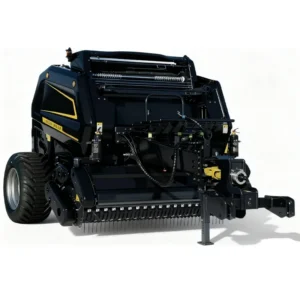
9YG-2.24D Classic — Sensor-Controlled Density System for Consistent Bale Quality on Sloped Ground
The 9YG-2.24D Classic shares the 2.24 m pickup width and 3922 kg structural mass of the Transcend series, with a sensor-controlled bale density system that monitors chamber pressure continuously throughout the bale formation cycle. On sloped terrain, this sensor system compensates for the asymmetric pressure distribution that occurs when the forming bale shifts toward the downhill side of the chamber — a common cause of density variation and off-round bales in highland Korean meadow conditions.
The hydraulic tailgate system on the Classic is designed for compatibility with a range of Korean compact and mid-size tractors, requiring a minimum auxiliary hydraulic flow of 15 litres per minute for smooth tailgate operation. The bale density range of 100–200 kg/m3 covers both dry hay and silage applications within the same machine configuration, making it a practical choice for Korean livestock farms that run multiple forage types across their baling calendar. Compatible Korean tractor brands include LS Mtron, TYM, and standard John Deere and New Holland models with conventional auxiliary hydraulic circuits.
Integration with the Tractor Hydraulic System: Flow, Pressure, and Circuit Design
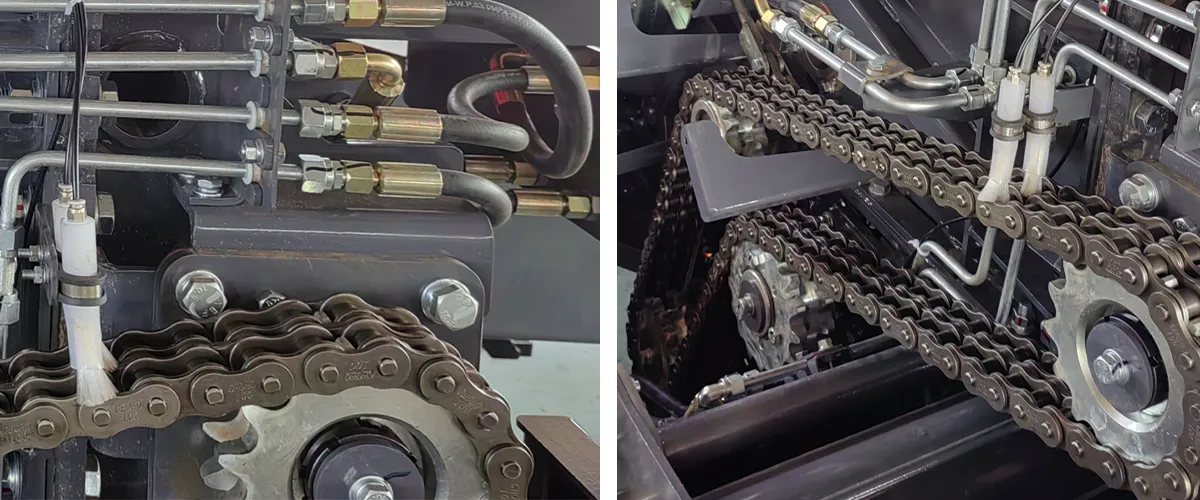
The buffer cylinder circuit on a round baler machine does not operate in isolation — it is powered by and connected to the tractor auxiliary hydraulic system through the standard remote hydraulic couplings on the rear of the tractor. Understanding how the tractor hydraulic output interacts with the baler circuit is important for operators who are connecting a new round baler to an older tractor where hydraulic system performance may have degraded from original specification.
For the 9YG-2.24D series, the minimum hydraulic system requirement is 15 litres per minute at 175–200 bar working pressure. Older Korean-market tractors in the 60–80 hp range from the 2005–2015 generation may have axial-piston pumps delivering 18–22 litres per minute at original specification, but pump wear can reduce this to 14–15 litres per minute or below — borderline for reliable tailgate operation. Fitting a flow meter between the tractor coupling and the baler circuit is a practical diagnostic for operators who experience slow or inconsistent tailgate behaviour, as it distinguishes between a hydraulic flow problem (tractor pump) and a cylinder seal problem (baler component) without requiring disassembly of either system.
The hydraulic hose connections between tractor and baler are another maintenance point relevant to the buffer system. Hose fittings on older tractors that have been repeatedly connected and disconnected over many seasons accumulate small amounts of dirt in the coupling faces, which then enters the hydraulic circuit on each reconnection. Particle contamination is the most common cause of accelerated wear in hydraulic cylinder orifices — the precision-drilled restriction passages that calibrate the buffer function. Using a hydraulic coupling protective cap on the baler side couplings during storage and transport significantly reduces contamination ingress between seasons.
Before connecting a round baler to any tractor for the first time in a season, operate the tractor hydraulic system at working temperature for 10 minutes with the remote circuit cycling through the full pressure range. This flushes any cold-thickened fluid from the hose runs, stabilises viscosity, and reveals any leakage at coupling faces before the baler is attached. This is particularly important at the start of Korean baling seasons in late spring, when overnight temperatures may still be cold enough to significantly increase hydraulic fluid viscosity in exposed hose runs.
Legal and Regulatory Context: Hydraulic Safety and Agricultural Machinery Standards
Republic of Korea
Round baler machines including their hydraulic systems are subject to MAFRA Agricultural Machinery Certification under the Act on Development of Agricultural Mechanization. Hydraulic circuits on certified agricultural implements must satisfy safety requirements that include maximum working pressure ratings, hose burst pressure specifications (minimum 4:1 safety factor on working pressure), and provision of hydraulic circuit diagrams in the operator manual. The Occupational Safety and Health Act (KOSHA) also applies to agricultural machinery used by employed farm workers, including provisions around hydraulic system guarding and documented inspection schedules. Operators running baling service businesses in Korea are subject to both MAFRA and KOSHA requirements.
Additionally, the Korean Clean Air Conservation Act — by restricting open-field residue burning — has made round baler ownership more economically justified for Korean livestock farmers, increasing the total fleet of operating machines and raising the importance of proper maintenance standards across the sector. MAFRA periodically publishes technical guidance on agricultural machinery maintenance that includes hydraulic system inspection requirements consistent with international ISO standards.
EU and Europe
Under Machinery Directive 2006/42/EC and the transitional EU Machinery Regulation 2023/1230, hydraulic components on agricultural machinery must be rated and marked for their intended working pressure. Hydraulic hoses on CE-marked implements must comply with EN 856 (wire-reinforced rubber hose) or EN ISO 1436 standards, which specify burst pressure, impulse cycle resistance, and bend radius requirements. The operator manual for CE-marked round balers must include a hydraulic circuit diagram, maintenance intervals for all hydraulic components, and the hydraulic oil specification. ISO 4413, the global hydraulic safety standard, is referenced in both EU and UK machinery safety frameworks and provides guidance on hydraulic hose installation routing to minimise failure risk.
Japan
The Japanese Industrial Standards (JIS B 8361) govern hydraulic cylinder construction and performance testing for industrial and agricultural applications. Round baler hydraulic cylinders exported to Japan are expected to meet or exceed JIS B 8361 requirements for bore tolerances, seal groove dimensions, and endurance test cycles. The Japanese Agricultural Mechanization Promotion Act requires that imported agricultural implements pass NARO performance testing, which includes hydraulic system reliability assessment under simulated field load cycles. Japanese buyers of round baler machines typically request JIS compliance documentation for the hydraulic cylinder assemblies as part of their pre-purchase technical review.
United States
ASABE EP455.1 provides engineering guidelines for hydraulic systems on agricultural equipment in the US, including flow rate, working pressure, and hose specification guidance. OSHA 29 CFR 1928 (Agricultural Operations) includes requirements for hydraulic system maintenance documentation on equipment used by hired workers. Round baler operators in the US conducting custom baling work as a commercial service are also subject to state-level agricultural worker safety regulations that may require documented equipment inspection records, including hydraulic circuit condition checks.
Australia
Under the Australian Model WHS Regulations and state Work Health and Safety Acts, agricultural plant including round balers with hydraulic systems is subject to documented risk assessment and maintenance record requirements. AS 4024.3 (Safety of Machinery — Hydraulic and Pneumatic Systems) provides the technical framework for hydraulic component safety requirements in Australia, aligned to ISO 4413. Agricultural machinery importers supplying the Australian market are expected to provide hydraulic circuit documentation and recommended maintenance schedules that satisfy these standards.
Compatible Components: PTO Shaft and Agricultural Drive Chain
The hydraulic buffer system operates alongside the mechanical drivetrain of the round baler machine — and the reliability of both systems depends on correct component matching and maintenance. For operators sourcing a complete round baler setup, the PTO shaft and internal drive chain are the two mechanical components that most directly affect drivetrain performance in the field conditions where the buffer cylinder is working hardest.
Agricultural PTO Shaft for Round Balers
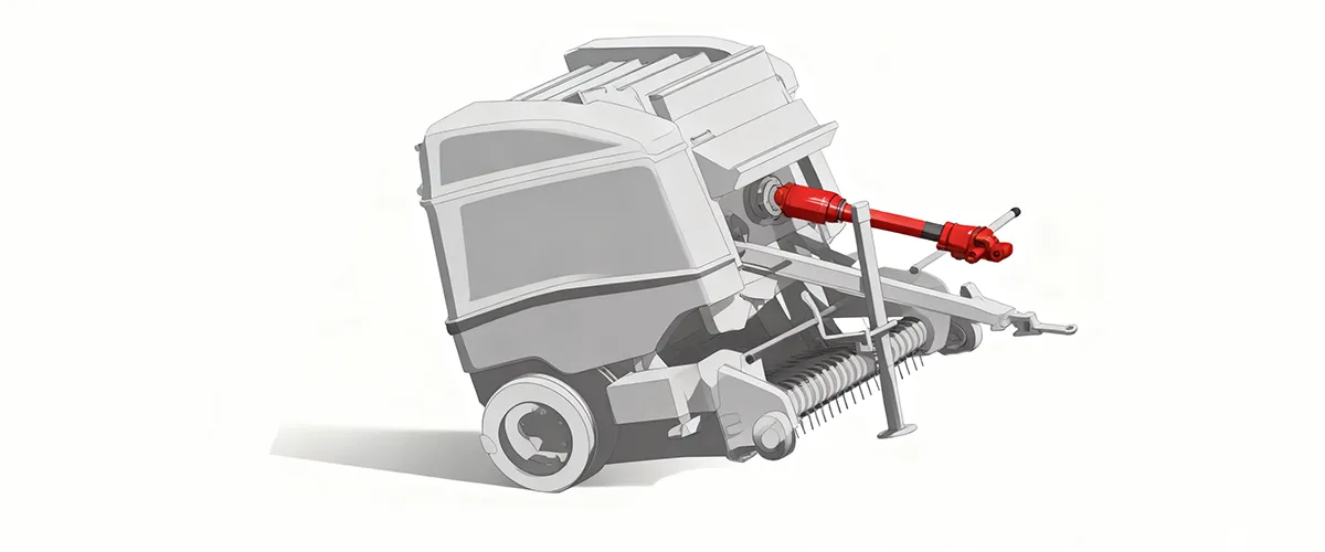
A properly rated Вал відбору потужності reduces the mechanical shock transmitted to the baler gearbox and through the chassis to the tailgate assembly. The EP-PTO shaft series for round balers uses a 1-3/8 inch Z6 spline, adjustable length 600–1200 mm, with an integrated friction-clutch overrun protector that absorbs sudden drivetrain load reversals — the same events that amplify shock loading at the tailgate on rough terrain. Torque transmission efficiency above 95% and compatibility with both SAE and EURO flange standards make this shaft a direct-fit choice for the 9YG-2.24D series on Korean tractor models.
Agricultural Drive Chain — High-Cycle Rough Terrain Specification
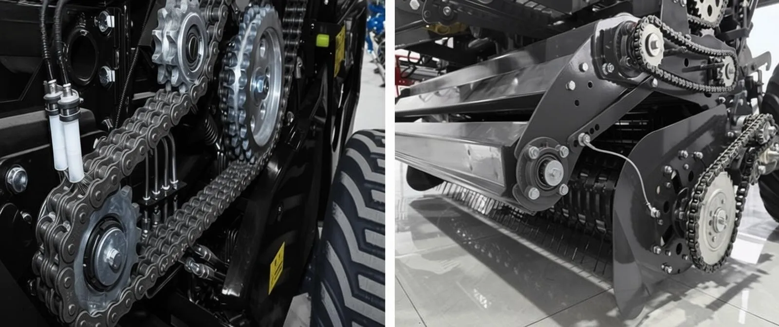
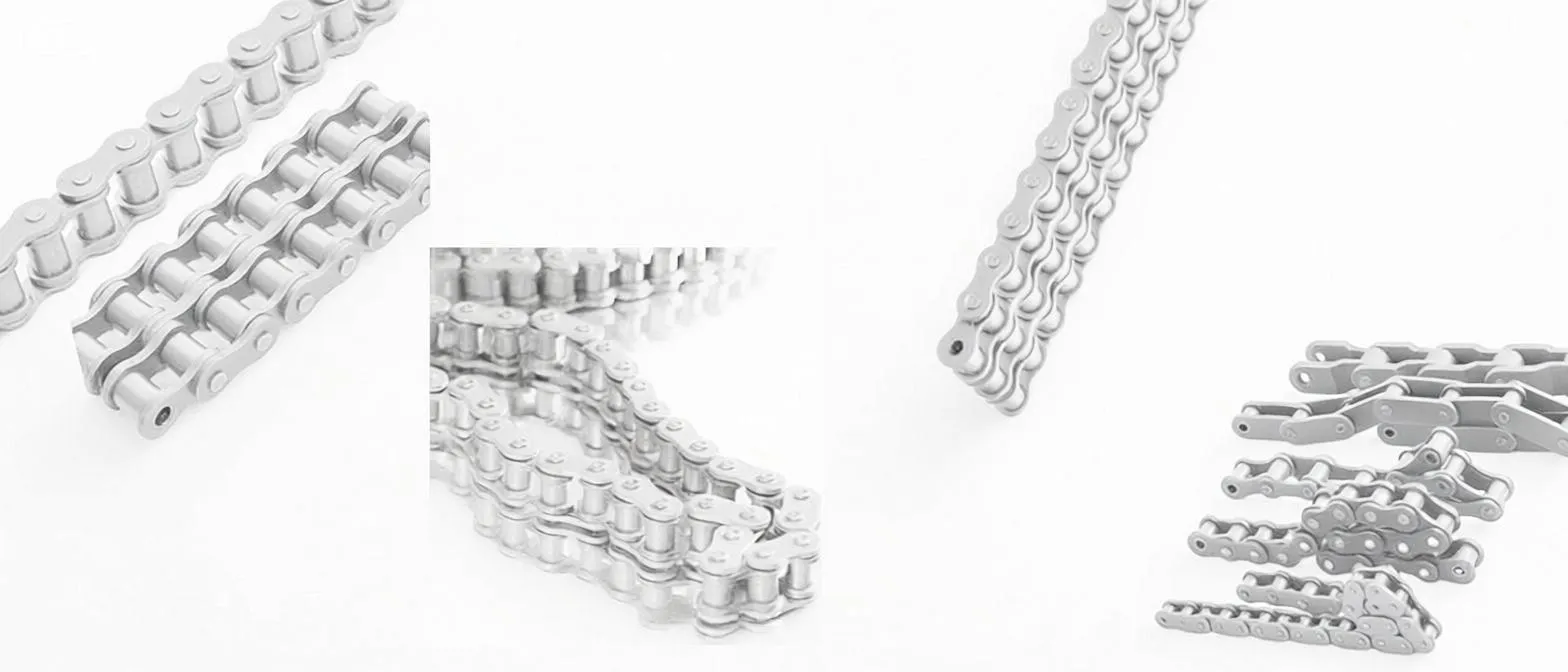
The drive chain inside the round baler chamber is the mechanical link between the gearbox and the compression rollers — and on rough terrain it absorbs the same shock load spectrum that challenges the hydraulic buffer system. ANSI #50 alloy steel chains rated to 60 kN minimum tensile, with hardened rollers at 10–12 mm diameter, provide the shock absorption and tensile strength needed for sustained performance on the high-cycle working pattern of Korean highland grassland baling. Maintaining correct chain tension — 10–15 mm sag at midspan — is as important for drivetrain shock management as for chain life.
Our Agricultural Machinery Manufacturing Background
Founded in 2013, our production enterprise has built a twelve-year track record in grassland machinery design and manufacturing. We produce a comprehensive line of round baler machines — from lightweight compact models suited to small hay baler applications on Korean highland parcels, through to heavy-duty silage balers for large-scale forage contractors — alongside disc mowers, twin-blade cutters, and raking equipment that covers the complete forage production cycle.
Over 60 production units operate across our facility, including CNC laser-cutting lines, automated robotic welding stations, and electrostatic powder-coating systems. Annual production capacity is 2,000 units. The entire operation runs under ISO 9001 Quality Management System certification. We hold independent import and export rights allowing direct supply to Korea, Japan, Australia, Europe, and North America without intermediary handling delays.
Our engineering team has specific experience designing for the slope, temperature, and tractor fleet conditions of Korean highland grassland operations — including tailgate hydraulic system specification for rough-terrain durability and bale density calibration for the forage species and moisture ranges typical in Korean mountain meadow environments. Technical enquiries about compatibility with existing Korean tractor models are welcome directly through our contact channel.
Frequently Asked Questions
What does a hydraulic buffer cylinder do on a round baler used for grassland operations in Korea?
Which round baler model is best for highland pasture terrain in Gangwon Province where slopes and rough ground are common?
What hydraulic oil specification should I use in my round baler buffer cylinder for Korean highland operating conditions?
What round baler parts should I keep in stock specifically for the hydraulic buffer cylinder during the Korean baling season?
Does the round baler hydraulic tailgate system need to meet specific legal standards for use in South Korea?
How does a round baler hydraulic buffer cylinder differ from the main tailgate lift cylinder and why do I need both?
Редактор: PXY