Cotton Stalk Baling | Operational Configuration | Round Baler Setup Guide
A practical operational guide for round baler machine operators, farm managers, and equipment procurement specialists who need to correctly configure pickup drum speed, ground speed, and chamber pressure settings when processing coarse, woody cotton stalks — covering the engineering principles behind each setting, the material systems that support correct configuration, and how machine specification affects the range of configurations available.
Cotton Stalk Setup
Operator Configuration Guide
1. Why Pickup Speed and Chamber Pressure Are the Two Most Critical Operator Variables in Cotton Stalk Baling
Most round baler machine operators learn their machine configuration from hay or cereal straw experience, where a relatively wide range of pickup drum speeds and tractor ground speeds produce acceptable results. Cotton stalks are different in almost every relevant physical parameter, and an operator who applies hay-field settings to a cotton stalk pass will encounter either repeated blockages, poorly formed bales, or accelerated component wear — often all three before the end of the first day. Understanding why the correct settings differ, and what machine parameters control those settings, is the foundation of productive cotton stalk baling without the downtime and frustration that accompany an unadjusted machine.
The two most directly controllable variables in any round baler application are ground speed — which determines how quickly crop enters the pickup assembly per unit time — and chamber pressure, which in a fixed-chamber machine is an emergent property of bale density target, roller drive torque, and the mechanical stiffness of the material being compressed. For cotton stalks, which are significantly stiffer and woodier than any grass crop, the correct relationship between these two variables is not intuitive from prior experience with flexible crops. This guide works through that relationship systematically, using the 9YG series round baler specifications as the concrete reference points for each configuration decision.
2. Cotton Stalk Physical Properties That Drive Configuration Decisions
Before adjusting any baler setting, operators need a clear picture of what makes coarse cotton stalks mechanically distinct from the crops most round balers were designed around. The main stem of a mature cotton plant at harvest has a lignified woody structure similar to a young tree branch, not a grass stem. Main stem diameters typically range from 12 mm in lighter varieties grown under dryland conditions to 28 mm or more in heavily irrigated cotton cultivars common in Uzbekistan, Pakistan’s Punjab, and China’s Xinjiang region. These woody stems do not bend and flow into the compression chamber the way grass or straw does — they break rather than bend, generating segments of varying lengths from 100 mm to 600 mm depending on the point of fracture relative to the branching nodes along the stem.
The branching architecture of cotton plants adds further complexity. Unlike cereal straw where the main stem is the primary material, cotton plants produce dense lateral branches that account for 40–60% of the total above-ground biomass. These branches break at irregular angles during pickup and feeder contact, creating an intake stream with highly variable segment geometry — some entering the chamber parallel to the rotation axis, others perpendicular, others at intermediate angles. This geometric variability is the underlying reason why chamber pressure fluctuates more in cotton stalk baling than in any other common round baler application, and why the operator’s ability to moderate the intake rate through ground speed adjustment is the single most important real-time control available during the operation.
Main stem diameter 12–28 mm, lignified to hardwood hardness at maturity. Requires 3–5× more feeder force than hay to redirect into chamber rotation. Standard spring-tine pickups deflect rather than grip at these dimensions.
Stalks break rather than bend at chamber entry. Segment lengths of 100–600 mm with random orientation in the intake stream. Irregular segments create pressure spikes at the chamber compression wall when they lock perpendicular to the roller array.
Residual cotton fiber at lateral branch nodes wraps aggressively around rotating components when nodes contact pickup tines, feeder rollers, or auger flights. Node fiber wrapping is the most common cause of sustained operational blockage in cotton stalk baling.
Post-harvest cotton stalks at 8–18% moisture are significantly drier than rice straw or hay at typical baling conditions. Lower moisture means stiffer material that requires more roller force to achieve the target bale density and less natural adhesion between layers inside the chamber.
3. Configuring Pickup Drum Speed for Coarse Cotton Stalks
In a round baler machine, the pickup drum speed is set by the PTO input shaft speed, which is controlled at the tractor through the PTO engagement speed selection — typically 540 r/min or 720 r/min at the tractor output shaft, geared through the baler’s own drivetrain to the actual pickup drum rotation rate. For most 9YG series models, the standard PTO input speed is 720 r/min. The 9YG-1.25A accepts a broader range of 540–1,000 r/min, which gives operators more flexibility when matching PTO speed to field conditions. In practice, the pickup drum tip speed — the tangential velocity of the tine or claw tips — is what directly determines how aggressively the pickup engages cotton stalks and at what rate material enters the feeder.
For coarse cotton stalks, the optimal pickup configuration is typically a lower drum tip speed than the machine’s rated maximum, combined with a reduced ground speed. The reason for this counterintuitive reduction is that a high drum tip speed in dense, woody material creates excessive impact energy at the pickup-to-stalk contact point — energy that breaks stalks into very short fragments rather than lifting whole or partially intact stalks. Very short fragments (under 150 mm) orient randomly in the intake stream and are particularly prone to creating the perpendicular-to-flow mat at the compression chamber inlet that leads to inlet jams. By reducing drum speed slightly — or equivalently, reducing ground speed to reduce the intake rate while maintaining drum speed — operators can encourage longer stalk segments that feed more predictably into the compression chamber and establish bale rotation more reliably at the core-building phase. On machines with 9YG-series PTO specifications, this translates to: if running at rated 720 r/min PTO, reduce tractor ground speed to 4–7 km/h during cotton stalk processing rather than the 10–15 km/h that might be used for hay. This keeps the pickup drum at its designed rotational efficiency while reducing the instantaneous material volume entering the feeder per minute.
4. Understanding and Configuring Chamber Pressure for Coarse Cotton Stalks
In a fixed-chamber round baler machine like the 9YG series, the operator does not directly set compression pressure in the way a hydraulic press operator might. Instead, chamber pressure is an emergent outcome of: the target bale density setting on the sensor-controlled monitoring system, the mechanical stiffness of the material being compressed, and the rotational torque available from the roller drive chain system. What the operator can control are the density target setting on the baler’s monitoring system and, indirectly, the intake rate that determines how quickly each layer of material is added to the growing bale. Understanding this indirect control is essential for configuring a round baler correctly for cotton stalks without damaging the drivetrain or producing unstable bales.
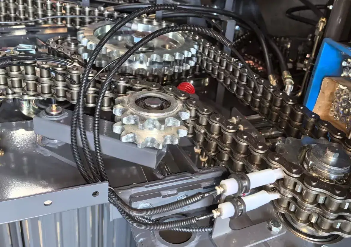
For coarse cotton stalks, the correct density target setting on the monitoring system is lower than what might be used for hay or rice straw. This is a setting that surprises many operators. The intuition is that denser bales are always better — more biomass per load, better economics for transport. But in cotton stalk applications, setting the density target too high creates two distinct problems. The first is that the roller drive chain system — typically 20A heavy-duty chain in the rear chamber of the 9YG series — experiences sustained peak torque that exceeds its design fatigue limit if the bale core is being compressed at full density before the initial core layer has established stable rotation. At the beginning of each bale cycle, the first material entering the chamber must establish rotation against the compression rollers. Dry, rigid cotton stalk segments resist this initial rotation more than flexible hay, and if the density target is set to maximum from the outset, the required roller force exceeds what the drivetrain can sustain without chain elongation or link fatigue. Setting the density target 15–25% below the rated maximum for the first three to four bale cycles of each session — then progressively increasing toward the target density as the operator confirms stable bale core formation — significantly reduces this fatigue risk.
The Chamber Pressure Spike Problem and How to Manage It
Even with correct density target settings, cotton stalk baling creates intermittent chamber pressure spikes that do not occur in flexible crop applications. These spikes happen when a large segment of main stem — particularly one with multiple lateral branch stubs — enters the chamber at a perpendicular orientation relative to the roller array and momentarily acts as a lever against the rotating bale surface. The physical effect is a brief but sharp increase in the torque required from the roller drive system, often visible as a momentary dip in tractor engine speed if PTO loading is monitored. In well-specified machines like the 9YG-2.24D S9000 with its 1,000 Nm rated gearbox torque and 20A heavy-duty rear chamber chain, these spikes are absorbed without lasting mechanical consequence. In lighter-specified machines, repeated pressure spikes of this type accelerate chain elongation and gearbox gear surface wear. The practical management strategy is to avoid high ground speed during the first 20–30 seconds of each new bale cycle — the period when the bale core is smallest and most vulnerable to chamber stall from a large stalk segment orienting incorrectly.
5. Manufacturing Structure: How Machine Design Determines Configuration Range
The range of pickup speed and chamber pressure configurations available to an operator is not infinitely flexible — it is bounded by the machine’s mechanical specification. Understanding the structural features that define these bounds helps operators know what adjustments are within safe operating parameters for their specific round baler machine and what settings risk component damage. The following section covers the principal structural subsystems in the 9YG series that directly interact with pickup speed and chamber pressure management in cotton stalk conditions.
Pickup Assembly Structural Design
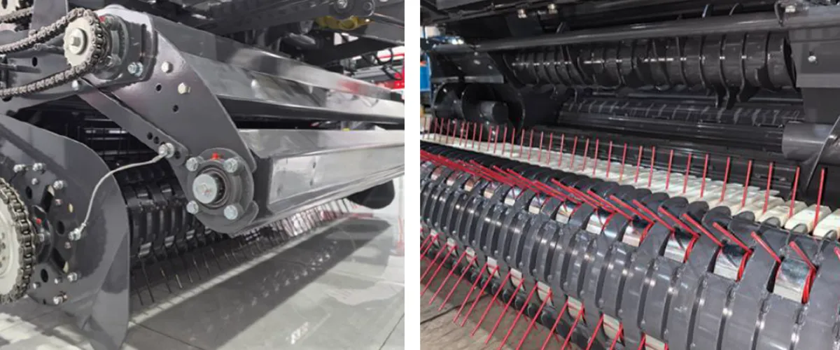
The pickup assembly must be structurally rated for the impact loads generated when hammer-claws engage rooted cotton stalks. The 9YG-1.0C’s 20-unit hammer-claw assembly operates with a downward-striking geometry that generates peak loads at the tine bar mounting during each claw engagement. The tine bar carrier is fabricated from structural steel with precision-bored bearing seats — the boring tolerance directly affects how long the tine bar runs true before wobble from bearing wear begins to affect pickup accuracy at the field edge. Operators who run at higher ground speed generate more claw impact events per operating hour, accelerating this wear. The 4–8 km/h recommended speed for cotton stalks is therefore not just an intake rate recommendation — it is also a mechanical protection parameter for the pickup assembly itself. At pickup drum speeds appropriate for 720 r/min PTO operation and 6 km/h ground speed, the claw impact frequency is within the design fatigue limit of the carrier bearing assemblies. At 12–15 km/h with the same drum speed, the impact frequency doubles and bearing fatigue life halves accordingly.
Feeder System and Anti-Clog Architecture
The feeder system’s structural design has direct implications for how the operator should respond when material flow irregularities occur during cotton stalk baling. On the 9YG-1.25 with its three-element auger-plus-roller-plus-drum feeder, a partial blockage at the chamber inlet is typically self-clearing within 3–5 seconds if the operator reduces ground speed to near-zero and allows the feeder to continue operating at PTO speed — the auger and roller continue working on the accumulated material and typically push it through the inlet without a manual clear. On simpler single-element feeders, partial blockages at the inlet tend to compact rather than clear, requiring a manual stop and inspection. Operators should ask their machine supplier to confirm the self-clearing behavior of the feeder system for their specific model before the cotton stalk season, and practice the ground speed reduction response during initial passes at low crop density before moving to full production speed.
Compression Chamber — Roller Array and Drive Chain
Inside the compression chamber, the 18-roller array of the 9YG-1.25 and 9YG-2.24D series provides a total of 18 active contact surfaces for bale rotation. For cotton stalk applications, the spiral groove surface profile on these rollers is particularly important: it maintains grip on dry, rigid stalk segments that would slip on a smooth roller face and stall bale rotation. When stall occurs — usually identifiable as a sudden sharp tractor RPM drop and an immediate absence of the characteristic sound of bale rotation inside the chamber — the correct operator response is to immediately disengage PTO and open the tailgate briefly to relieve chamber pressure before re-engaging. Attempting to push through a stall with increased PTO throttle subjects the rear chamber 20A chain to sustained above-rated torque that will accelerate fatigue elongation or, in severe cases, cause link failure. The gearbox on machines like the 9YG-2.24D S9000 includes a safety torque limiter as standard, which provides automatic protection against sustained overload; on machines without this feature, the operator’s judgment is the only protection.

6. Material System: Component Specifications That Support Configuration Performance
The ability to safely operate a round baler at the configuration settings recommended for cotton stalks — reduced ground speed, lower initial density target, active chamber pressure management — depends on the mechanical quality of the components handling the resulting load distribution. The following table summarizes the material specifications in the 9YG production series that are most directly relevant to pickup speed and chamber pressure management in coarse cotton stalk service.
7. Step-by-Step Configuration Protocol for Coarse Cotton Stalk Round Baling
The following protocol consolidates the configuration guidance above into a practical pre-session and in-session sequence for operators using the 9YG series round baler in cotton stalk applications. This protocol applies to both the 9YG-1.0C (hammer-claw pickup) and the 9YG-1.25 (with interchangeable pickup set to hammer-claw). Operators using the 9YG-2.24D series in windrowed cotton stalk conditions should apply the same ground speed and density target principles, adapting them to the specific PTO speed setting available on their tractor.
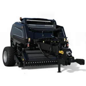
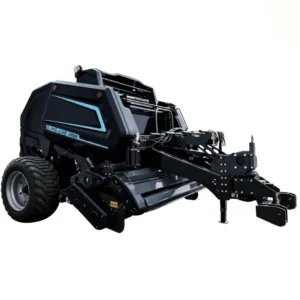
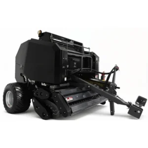
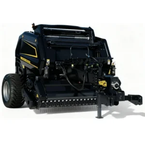
8. Round Baler Models for Cotton Stalk Configuration
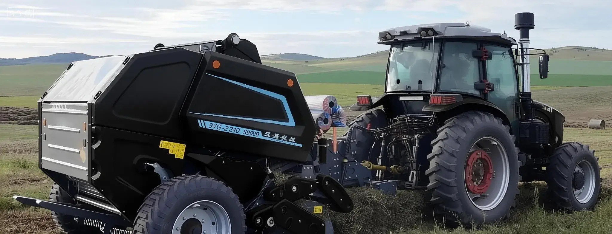
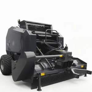
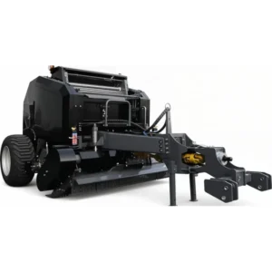
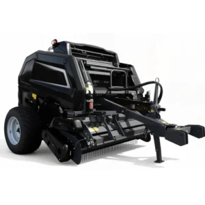
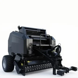
The following models support the pickup and chamber pressure configuration protocols described above. Specifications are from the manufacturer’s published data sheets.
9. Regulatory Context: Gearbox Standards and Cotton Stalk Disposal Laws Across Key Markets
The configuration guidance in this article applies broadly across cotton-growing regions, but the regulatory environment that makes cotton stalk baling a compliance necessity — rather than merely an economic opportunity — varies by jurisdiction. The following summary covers the primary regulatory context in markets where this article’s guidance is most directly applicable.
South Korea — Clean Air and Agricultural Machinery Standards
South Korea’s Clean Air Conservation Act (대기환경보전법) prohibits open burning of agricultural residue, including cotton stalks, during designated enforcement periods in Jeolla, Chungcheong, and Gyeonggi provinces. For operators seeking subsidy support through the Rural Development Administration (RDA) equipment financing program (농기계 구입자금 융자 at 1.5–2.0% per annum), machinery must meet Korean Agricultural Machinery Safety Standards under KS B 6007 and the Agricultural Mechanization Promotion Act (농업기계화 촉진법). Specifically for round baler gearboxes, Korean standards reference general agricultural machinery safety requirements for rotating transmission components and PTO shaft guarding that align with but are not identical to the international GOST or CE frameworks. Machines imported for Korean subsidy applications require third-party technical inspection documentation in the format specified by the Korean testing authority designated under the Agricultural Mechanization Promotion Act.
Uzbekistan and Central Asia — GOST and EAC Certification
Agricultural machinery operating in Uzbekistan, Kazakhstan, Kyrgyzstan, and Armenia must carry EAC (Eurasian Conformity) marking under technical regulation TR CU 010/2011, which covers machinery safety requirements including gearbox protection, PTO shaft guarding, and bale ejection zone protection. The gearbox on the round baler must demonstrate conformity with the safety requirements specified in this technical regulation — in practice, this means the gearbox housing must be fully enclosed with no exposed rotating components accessible to the operator during normal operation. GOST R 53504 provides the underlying Russian-origin standard that most EAC agricultural machinery conformity assessments reference for performance and safety requirements. Burn prohibition for cotton stalks is enforced under Uzbekistan’s State Committee of Ecology regulations and Kazakhstan’s Environmental Code and Air Protection Law, creating the compliance driver for mechanical baling.
European Union — Gearbox Safety Under EN 703 and CE Marking
In EU cotton-growing regions — primarily Greece’s Macedonia and Thessaly, and Spain’s Andalusia — agricultural machinery must carry CE marking under Machinery Directive 2006/42/EC. For round balers specifically, the harmonized standard EN 703 (safety of agricultural machinery — crop harvest and processing machinery) specifies requirements for the bale ejection zone, PTO shaft guarding under EN 12965, and gearbox housing protection. The gearbox casing must prevent inadvertent operator contact with rotating components during normal operation and maintenance positions defined in the operator manual. Safety sign requirements follow EN ISO 11684. Open burning of cotton stalks is restricted under EU member state implementing regulations of Directive 2008/50/EC on ambient air quality, and under CAP Good Agricultural and Environmental Conditions (GAEC) which conditions support payments on responsible residue management.
India — SMAM Program and BIS Standards
In India’s major cotton states — Maharashtra, Gujarat, Telangana, and Andhra Pradesh — the National Green Tribunal (NGT) has issued orders prohibiting open burning of agricultural residue including cotton stalks in multiple jurisdictions. The Sub-Mission on Agricultural Mechanization (SMAM) provides subsidy support for qualifying baling equipment purchased by Indian farmers. Machinery must meet Bureau of Indian Standards (BIS) requirements applicable under the Agricultural Machinery Act framework. Round baler gearboxes must meet IS 9578 (general safety requirements for agricultural and forestry machinery) and related BIS standards for rotating power transmission safety. For imported machines entering the Indian market, a BIS certification or recognized third-party equivalence assessment is typically required to qualify for SMAM scheme subsidy eligibility.
10. Compatible Drive Components: Agricultural PTO Shaft and Agricultural Chain
Correct configuration of pickup speed and chamber pressure protects the round baler machine’s own drivetrain components — but only if the connecting components between the tractor and the baler are also correctly specified. An undersized or worn Agricultural PTO Shaft for round balers is a common failure point in cotton stalk service because the sustained high-torque demand at low ground speed exceeds the continuous rating of shafts sized for hay applications. A purpose-rated baler PTO shaft with integrated overrunning clutch prevents reverse-shock damage to the tractor gearbox when chamber stall events cause momentary reversal of the baler drivetrain. Agricultural chain specified to the 16A (feeder) and 20A (rear chamber) grades used in the 9YG factory configuration ensures that the drive system can operate within the configuration parameters described in this guide without premature chain fatigue.
Overrunning clutch and shear-bolt torque limiter options to protect both baler and tractor against chamber stall reverse-shock. 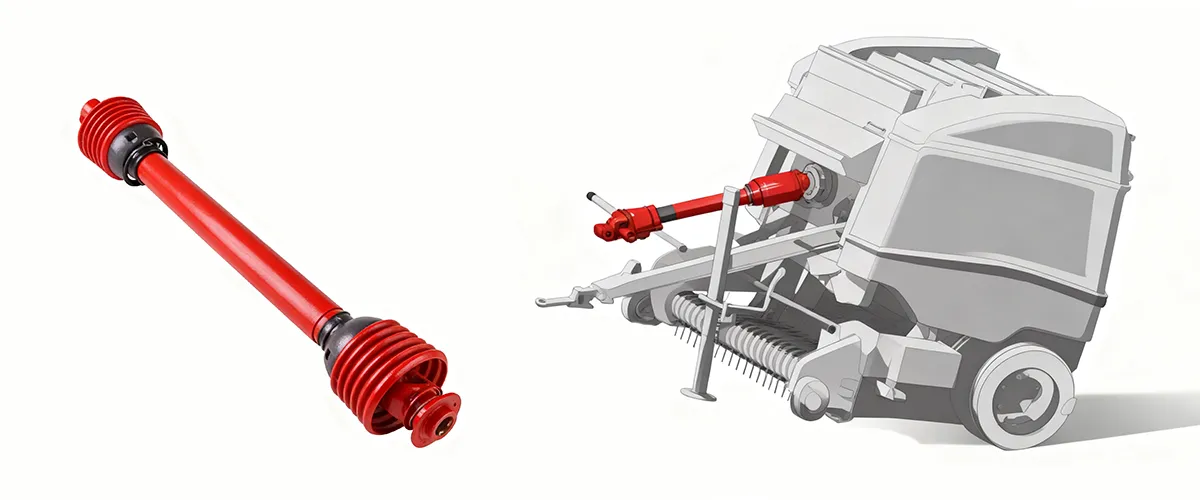
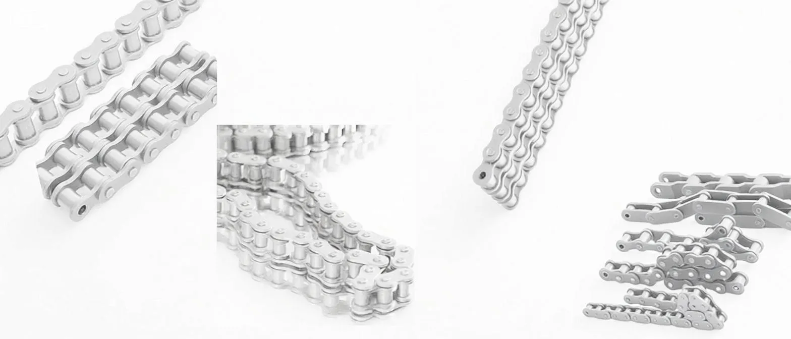
Matching the factory chain specification is essential for maintaining the drive system’s ability to handle the configuration parameters described in this guide. Non-specification chain in lighter grades fails prematurely when chamber pressure management protocols are applied in woody material. Available as complete machine replacement kits matched by baler model.
Frequently Asked Questions
संपादक: पीएक्सवाई