Technical Deep-Dive | Farm Equipment Education
What Happens Inside a Round Baler During the Baling Process?
A step-by-step breakdown of how a rotopressa collects, compresses, wraps, and ejects a finished hay bale — covering action mechanisms, structural engineering, material systems, and real-world agricultural applications across Korean and global farming contexts.
Quick Summary
① A round baler picks up cut crop from windrows using a spring-tooth pickup reel, feeds it through a metering system, and builds it into a cylindrical bale inside a variable-chamber compression zone.
② Once the bale reaches the target diameter — monitored by density sensors — the baler automatically activates the net-wrapping or twine-binding mechanism to secure the bale.
③ The rear gate opens hydraulically, the finished bale rolls out, and the chamber immediately resets for the next baling cycle — all while the tractor continues moving forward.
Understanding the Round Baler: Why the Internal Process Matters
For farmers working with hay, rice straw, wheat straw, corn stalks, or pasture grass — whether on the flat plains of South Korea’s Chungcheong provinces or on rolling terrain in Jeollanam-do — the rotopressa has become one of the most strategically important pieces of equipment in the harvest lineup. Yet most operators interact with the machine primarily at the operator level: hitching up, engaging the PTO, and collecting the finished bales. What happens mechanically between the crop entering the pickup header and the wrapped bale rolling out the rear gate is a surprisingly intricate sequence of coordinated mechanical events. Understanding each stage not only deepens your appreciation of the engineering involved, but also helps you troubleshoot problems, optimize settings, and select the correct round baler machine for your specific crop and field conditions.
This article walks through every phase of the baling process in sequence — from crop pickup through density monitoring, wrapping, and ejection — and explains the structural and material engineering that makes each phase work reliably. Along the way we reference specific models in the product range to illustrate how different design approaches address different operational needs, from the compact small round baler suited to lower-horsepower tractors all the way to heavy-duty machines targeting large-scale commercial operations.
Whether you are an experienced crop farmer in Korea evaluating your next equipment purchase, a new entrant trying to understand the difference between a round hay baler and other bale formats, or an agronomist advising clients on machinery investment, this guide provides a technically grounded, readable explanation of what the machine actually does — and why each design choice matters in practice.
Phase 1 — Crop Pickup: From Windrow to Intake
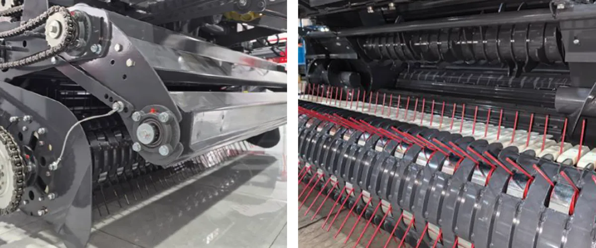
The baling process begins at ground level, where the crop — already cut and raked into a windrow — contacts the round baler parts that form the pickup header. The standard pickup mechanism on most modern round balers uses a spring-tooth reel: a rotating drum carrying rows of hardened steel tines arranged in a helical pattern around the drum axis. As the drum rotates (typically driven via the baler’s gearbox from the tractor PTO), the tines sweep upward from below ground level, engaging the windrow and lifting the crop into the intake throat.
On the 9YG-2.24D series models, the pickup width is 2,240 mm — a deliberate engineering choice that balances two competing requirements. A wider pickup covers more windrow material per meter of forward travel, increasing throughput and reducing the number of passes needed to clear a field. At the same time, a pickup that is significantly wider than the tractor’s wheel spacing risks disturbing crop outside the intended windrow, picking up soil or stones that can damage the compression chamber. The 2,240 mm dimension places the outer tine paths just inside the tractor’s tire tracks on standard wheelbase configurations, keeping the harvested material clean.
Two principal pickup geometry options exist in current round baler designs. The cam-track pickup uses a fixed cam rail that controls tine retraction timing — tines extend outward to grab crop, then retract below a stripper plate to release material cleanly into the intake. The alternative approach, used on the 9YG series, is a camless pickup architecture: rather than relying on a cam profile to time tine retraction, the tines are designed to follow a specific geometric path relative to the crop flow, with a stripper bar geometry that mechanically separates the incoming material from the tine tips without requiring the cam hardware. This design reduces the number of wear-prone moving components in the pickup unit and lowers the probability of cam-track wear causing inconsistent tine retraction — a common failure mode that leads to crop wrapping around the pickup shaft.
The 9YG-1.0C and 9YG-1.0 series take this further, with an “axial-flow semi-forced feeding mechanism” that specifically addresses the intake flow path. Rather than relying entirely on the pickup tines to push crop up and into the intake, the axial-flow design uses the rotational momentum of the incoming crop mass itself to maintain continuous flow through the intake throat, reducing the back-pressure against the pickup tines during dense windrow conditions. In Korean rice straw harvesting — where post-combine windrows can be particularly dense and moist — this feeding geometry measurably reduces the frequency of intake blockages that require operator intervention.
Phase 2 — The Feeding Mechanism: Metering Crop Into the Chamber
Once the crop clears the pickup header, it enters the feeding zone — a short but mechanically critical section that transitions the material from horizontal ground-level travel to the vertical or angled trajectory required to enter the compression chamber. The primary components in the feeding zone vary between baler families.
On the 9YG-2.24D series, the feeding zone uses a combination of tine-roller and cylinder-roller elements. The tine-roller presents a row of radially mounted tines that agitate and loosen the incoming crop flow, preventing bridging — the tendency of long-fiber materials like cereal straw or legume hay to form a compacted arch across the intake aperture that stops material movement. The cylinder-roller follows immediately, providing a positive-drive surface that grabs the loosened material and accelerates it into the chamber entrance. Together, these two elements create a semi-forced metered flow that decouples the chamber fill rate from the tractor’s forward travel speed within reasonable limits, allowing consistent bale formation even as the windrow density varies across the field.
The 9YG-1.25 model adds an auger as the first element before the tine-roller and drum combination. An auger in this context serves a laterally distributing function: crop entering the intake from across the 2,240 mm pickup width needs to be redistributed laterally to fill the 1,250 mm compression chamber width evenly. Without this redistribution step, crop from the outer edges of the pickup tends to bunch toward the center of the intake, creating an off-center load on the chamber that produces bales with uneven density — lighter at the edges, denser in the core. The auger’s helical flight gently pushes outer-edge material toward the ends of the chamber width, achieving lateral uniformity before the material enters the compression zone.
Feeding mechanism geometry is one of the most consequential engineering choices in round baler design for Korean conditions, where rice straw — harvested after combine threshing in autumn — is notoriously challenging to bale. The straw tends to be short-chopped, moist, and heavy with grain chaff, creating clumping behavior that differs significantly from dry hay. Balers designed primarily for long-fiber hay may suffer repeated blockages in rice straw applications, whereas the semi-forced feeding systems described above maintain throughput consistency across a much wider range of crop conditions.
Phase 3 — The Compression Chamber: How a Cylinder Bale Forms
The compression chamber is the heart of the rotopressa, and understanding how the bale actually forms inside it separates the variable-chamber roller design from other approaches. On the 9YG series, the compression chamber is classified as a roller-type variable chamber — meaning the chamber boundary is not a fixed shape but expands as the bale grows, defined at all times by the array of driven rollers arranged around the chamber’s circumference.
The 9YG-2.24D uses 18 rollers in its chamber, each with a diameter of φ222 mm, spanning a chamber width of 1,400 mm. The chamber diameter can grow up to φ1,200 mm — producing a finished bale of φ1,300 mm × 1,400 mm dimensions (the bale is slightly larger in diameter than the chamber diameter because the net wrap or twine adds some bulk and the bale undergoes a degree of elastic relaxation after the gate opens). The 9YG-1.0 uses 16 rollers across a 1,000 mm chamber width, producing a smaller bale (φ1,100 mm × 1,000 mm) appropriate for smaller tractors and easier-to-handle bale weights.
As crop enters the compression zone through the intake, it contacts the rotating rollers. Each roller rotates at a surface speed that is faster than the incoming crop’s travel velocity. This speed differential creates a frictional drag that begins to impart rotation to the crop mass — what engineers call the bale core formation phase. During the first few seconds after the chamber starts filling, the small mass of crop inside tumbles freely, being dragged around by roller contact. Once the tumbling mass accumulates enough material that it begins to resist the roller drag, a self-sustaining rotation is established: the crop mass rotates as a unit, each rotation adding a new layer of crop from the intake. This is the layer-by-layer buildup mechanism that creates the characteristic concentric ring structure visible when a round bale is cut in cross-section.
The key variable throughout this phase is the pressure balance between the bale’s growing diameter and the rollers’ resistance. In a variable-chamber design, the rollers are spring-loaded or hydraulically tensioned so that as the bale diameter increases, the rollers yield outward — maintaining continuous contact pressure against the bale surface. The tension in this system directly determines bale density: higher roller tension produces denser bales, and the 9YG-2.24D is rated for 100–200 kg/m³ bale density, a range that accommodates everything from dry wheat straw (toward the lower density bound) to wet pasture silage (toward the upper bound). The S9000 variant of the 9YG-2.24D uses dual-side 20A heavy chain in the rear chamber section, which increases compression pressure and allows bale densities reaching the equivalent of 500–1,000 jin (approximately 250–500 kg) per bale.
Productivity across the full range is 40–100 bales per hour, depending on windrow density, forward travel speed (5–35 km/h operating range), and the bale density setting. At the high end of this range — large windrows, higher travel speed, lower density setting — the machine can produce a new bale approximately every 36 seconds. This cycle time is a significant competitive factor for Korean farmers working against harvest weather windows, where the difference between completing a field in one afternoon versus two can determine whether bales are made before rain.
Bale Density Control: How the Machine Knows When the Bale Is Ready
One of the most operator-relevant questions about the baling process is: how does the baler know when the bale is large enough to wrap and eject? The answer in modern round baler machines is sensor-based diameter monitoring. The 9YG series uses sensor-controlled bale density management, where a mechanical sensor arm contacts the outer bale surface as it grows. When the sensor arm reaches the target angle corresponding to the set bale diameter, it triggers the automatic net-wrapping system to activate.
The sensor signal triggers a sequence of automated events. First, the tractor operator (or an automated system on premium models) receives a cab signal indicating that wrapping has begun. Second, the net-wrap or twine mechanism activates — described in detail in the next phase. Third, once wrapping completes and the bale is fully secured, the hydraulic gate-open signal is enabled, and the operator presses the gate-open control. On the 9YG-2.24D series, the rear gate hydraulics use H-type compression fittings that increase hydraulic pressure capacity, making the gate open faster and more positively than standard fittings. A buffer cylinder on the gate dampens the closing motion, preventing the sudden impact that otherwise causes frame fatigue cracks at the gate hinge points — a known maintenance issue on machines without this buffering feature.
The practical importance of accurate density sensing cannot be overstated for consistent bale quality. In Korean rice straw baling — where the straw moisture content at harvest can vary from 15% to over 30% depending on post-harvest drying time and weather — a bale that is undersized at ejection will be too light and loose for efficient stacking, while an oversized bale may exceed the lifting capacity of common round bale handlers. Correctly calibrated sensor control directly determines whether the bales coming off the field are a consistent, marketable product or a variable mix of sizes.
Phase 4 — The Wrapping Mechanism: Securing the Finished Bale
Once the density sensor confirms the bale has reached the target diameter, the wrapping system activates. All models in the 9YG series use net wrapping as the standard binding method, and this is the dominant choice in modern commercial round balers worldwide for several well-established reasons. Net wrap binds the bale with a continuous spiral of polypropylene mesh rather than individual lengths of twine, producing a bale that holds its shape more tightly, sheds rain more effectively, and withstands the mechanical handling of a round bale loader without deforming. For Korean farms baling rice straw for silage — where an airtight surface film is then applied by a bale wrapper — a net-wrapped bale provides the smooth, consistent outer surface required for clean silage film adhesion.
The net is fed from a roll mounted at the baler’s front or upper frame section. A series of feed rollers and a spreading mechanism guide the net edge across the full width of the bale chamber. As the bale continues to rotate inside the chamber (the chamber rollers keep spinning throughout the wrapping phase), the net is drawn in and wraps helically around the bale surface. The number of net wraps applied is preset on most machines — typically two to four overlapping passes — and is controlled by a metering wheel on the net feed system that counts the number of net rotations per bale. The net specification on the 9YG-2.24D is 2,000 m × 1.4 m per roll, which is matched to the 1,400 mm chamber width.
After the set number of wraps is completed, a cutting mechanism — either a mechanical knife or a tear-off bar — severs the net. The cut edge is held against the bale surface by the final wrap tension, preventing the net from unraveling as the gate opens. This cutting action is one of the most wear-sensitive steps in the baling cycle; the knife must be kept sharp to produce a clean cut, as a ragged net cut creates loose net ends that can catch on subsequent incoming material and cause intake blockages. Routine knife sharpening or replacement is one of the first-line maintenance items on any net-wrap baler.
The entire wrapping cycle typically takes 8–15 seconds depending on the bale rotation speed and the number of wrap passes set by the operator. During this period, the baler is still moving forward but no new crop is entering the chamber — the intake feed roller disengages or the pickup is raised. This brief pause accounts for roughly 15–20% of the total baling cycle time and is the primary reason why net-wrap balers have a slightly lower theoretical throughput than twine-tie balers in ideal conditions, though the superior bale quality of net wrapping more than compensates for this in most Korean and global commercial operations.
Phase 5 —Manufacturing Structure: How the Machine Is Built
The structural engineering of a rotopressa must reconcile two competing demands: the machine must be heavy enough and rigid enough to withstand continuous high-load baling operation, but light enough to be towed safely by tractors in the specified horsepower range and maneuvered efficiently in the field. The 9YG-2.24D S9000 weighs 3,922 kg in its standard configuration, while the S9000 Classic variant comes in at 4,312 kg and the S9000 Transcend at 4,570 kg — the weight differences reflecting incremental structural upgrades in the frame, traction system, and gearbox specification rather than fundamental changes in the baling mechanism.
The main frame is fabricated from structural steel sections, cut using CNC laser cutting equipment and formed using CNC press-bending lines before robotic welding. This manufacturing sequence is significant because CNC-cut and CNC-bent components have tighter dimensional tolerances than manually cut or hammer-formed parts, which means the welded frame geometry is more consistent between individual machines. For a baler, frame geometry consistency directly affects how parallel the chamber rollers are to each other — a critical parameter, because rollers that are out-of-parallel create uneven bale density zones and accelerate bearing wear at the roller shaft ends.
The chassis uses a tandem-axle configuration with 2,600 mm wheelbase (9YG-2.24D) or 2,450 mm (9YG-1.25 series), providing a stable footprint when the machine is parked and a low roll angle during transport. The wheelbase also determines the turning radius when combined with the drawbar hitch geometry — a factor of considerable practical importance in Korea’s smaller-scale paddy field environments, where field headlands are often narrow and the ability to turn the tractor-baler combination in a short distance without damage determines operational efficiency.
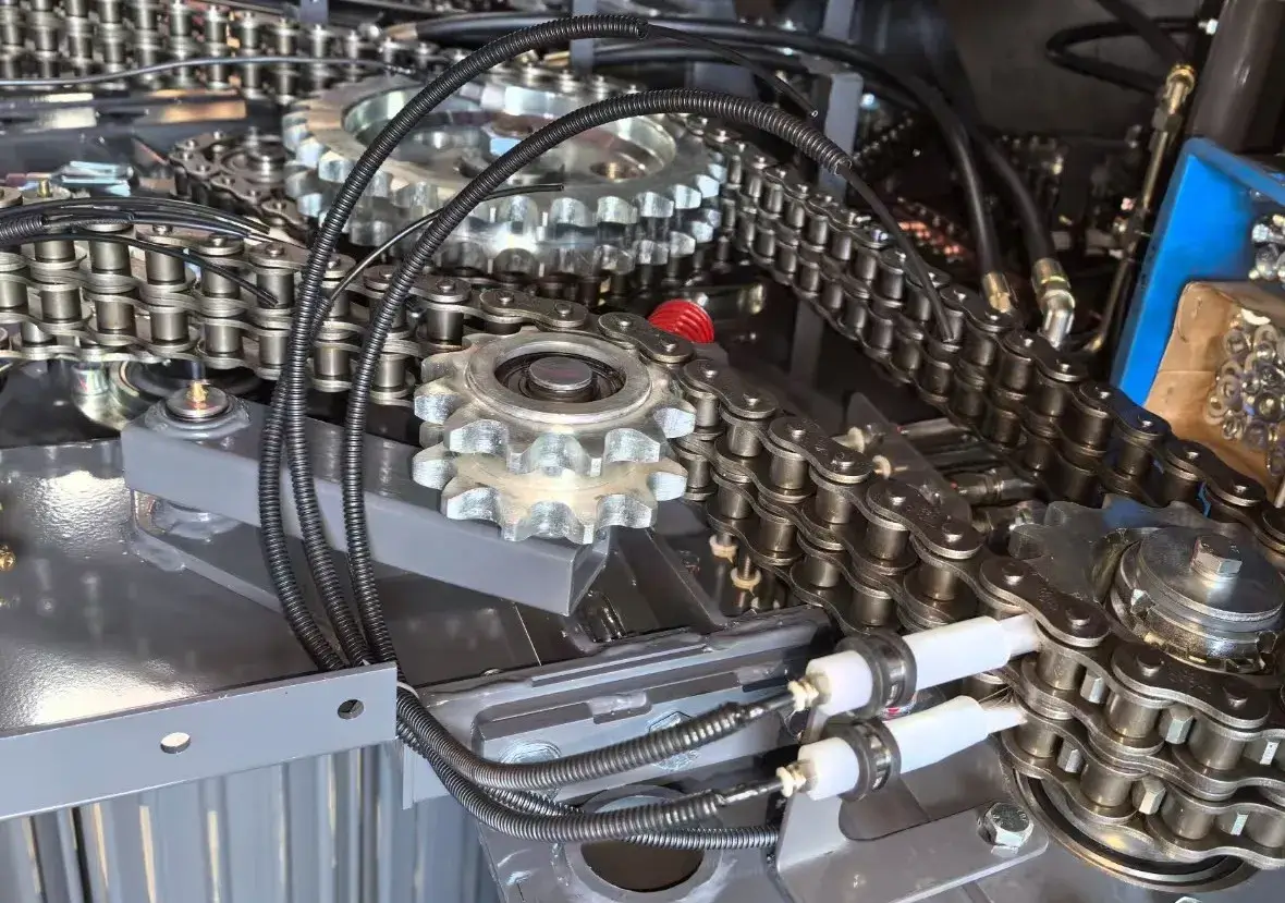
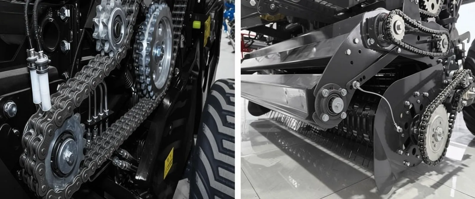
The rear gate — which carries a significant portion of the total machine weight and experiences repeated opening-and-closing impact loads — is one of the highest-stress structural elements. On the S9000 Classic and Transcend variants, the rear gate uses a dual-sided sprocket chain transmission for the chamber rollers mounted in the gate section. This design distributes the drive torque across both sides of the chamber rather than through a single central chain, reducing the torque loading on each individual chain run and extending chain service life. The dual-sided chain arrangement also reduces the lateral bending moment on the gate frame during baling, as the drive forces are balanced left and right rather than applied asymmetrically from one side.
Phase 6 —The Round Baler Gearbox and Drivetrain: Power Transmission Architecture
IL round baler gearbox is the mechanical hub that takes the rotational power from the tractor’s PTO shaft and distributes it to all the driven elements of the baler — pickup reel, feed rollers, compression chamber, and wrapping mechanism. The standard PTO speed for all 9YG series models is 720 r/min (with the 9YG-1.25A also accommodating 540 r/min), matching the two most common tractor PTO output speeds in global markets. The gearbox multiplies or divides this speed as needed for each driven component: the pickup reel typically rotates slower than the PTO shaft, while the chamber rollers may run at higher surface speeds to generate the frictional drive needed for bale formation.
The S9000 Transcend variant introduces a “dual compound gearbox” as a distinguishing feature. This gearbox design connects directly and rigidly to the drawbar hitch frame, and its key capability is the ability to rotate left or right up to 90 degrees relative to the baler main frame. This articulation means that when the tractor turns during a field headland turn, the gearbox and the PTO shaft angle can accommodate the turn geometry without requiring the operator to disengage the PTO — a safety and convenience advantage that substantially reduces the risk of PTO shaft damage during tight field turns. Without this feature, operators on standard balers must either slow down and disengage PTO before each turn (losing time) or accept the risk of overloading the PTO shaft joint if turning sharply at power.
The S9000 Transcend also incorporates an independent safety torque PTO shaft — a sacrificial shear bolt or friction clutch assembly positioned between the tractor PTO output and the baler gearbox input. If a sudden overload occurs (as when a stone or dense soil clump enters the baler through the pickup), the safety shaft absorbs the shock load and prevents the spike torque from reaching the chamber components. This protection is analogous to the shear bolt protection on a mower cutter bar, and it is the first-line protection for the more expensive internal drivetrain components.
All 9YG series balers use a trailing hitch connection , meaning the baler rolls on its own wheels behind the tractor rather than being mounted on the tractor’s three-point linkage. This arrangement allows a heavier machine with greater chamber capacity than a linkage-mounted design, and it keeps the baler’s weight off the tractor’s rear axle — important for front-axle traction and steering feel on sloped paddy field embankments in Korea’s rice-producing regions.
Phase 7 —Material Systems: What the Machine Is Made Of and Why It Matters
Material selection across the key wear components of a round baler determines both service life between overhauls and total operating cost over the machine’s working life. The following breakdown covers the primary material systems in the 9YG series.
Compression Rollers
Each of the 18 compression rollers (φ222 mm) uses a surface-hardened steel tube with continuous spiral fins or flutes on its outer surface. The fins serve two purposes: they increase the effective contact area between the roller surface and the bale material (improving traction on the bale surface for rotation), and they create a self-cleaning mechanical action that sheds loose material from the roller face during operation. The roller tube walls are thickened at the shaft end bearing seats to resist the radial loading imposed by the spring tension system. Roller bearing replacement is one of the most common scheduled maintenance items, and the accessibility of the bearing housings from the exterior of the machine is a significant practical design consideration.
Drive Chains
The chamber drive chains on the S9000 and S9000 Classic use 20A heavy-duty chain (the A designation indicating a standard pitch reinforced chain). On the Transcend model, the rear chamber sections use 20A chain on dual-sided sprocket drives. Chain material is case-hardened medium-carbon steel with precision-ground link plates. Chain lubrication is critical to service life; most Korean operators run the machine with an automatic chain oiler or perform manual greasing every 8–10 operating hours. Chain wear elongation beyond 3% of nominal pitch requires replacement to maintain consistent compression timing and prevent roller speed variation across the chamber width.
Pickup Tines
Spring-tooth pickup tines are manufactured from oil-quenched high-carbon spring steel, hardened to approximately HRC 45–50. This hardness provides the yield strength needed to deflect elastically when contacting a stone or soil clump, then return to position, rather than permanently bending. Tine loss rate in Korean paddy field conditions is higher than on dryland crops because post-harvest paddy surfaces often contain embedded stones and compressed soil ridges from tractor tire tracks. Operating with a tine count below specification — even a few missing tines — creates pickup gaps that leave rows of unprocessed crop in the field and reduce effective throughput. Tine inventory management is a routine part of Korean baler maintenance practice.
Frame & Structural Steel
The main frame sections are cut from Q345B structural steel plate (a Chinese national standard equivalent to S355 JR in European notation or ASTM A572 Grade 50 in US notation). This steel grade provides a yield strength of approximately 345 MPa, which is the minimum specification for structural members carrying the combined weight of a 4,000+ kg machine plus the dynamic baling loads. Critical weld joints in the frame receive post-weld shot-blasting before the electrostatic paint system is applied — shot-blasting removes weld scale and mill scale that would otherwise act as corrosion initiation sites under the paint layer.
Hydraulic System Components
The hydraulic system for gate operation uses H-type ferrule fittings on pressure lines. Ferrule fittings provide a mechanical seal at the tube end rather than relying on thread engagement alone, which makes them substantially more reliable under vibration than standard NPT or metric thread fittings. System pressure capability with H-type fittings is higher than with standard fittings, which is why gate operation speed improved on the S9000 Classic and Transcend — the higher allowable line pressure allows a smaller actuating cylinder to generate the same gate force, and the smaller cylinder volume means faster extension and retraction.
Phase 8 — Bale Ejection and Cycle Reset
After the net-wrapping cycle is complete, the operator initiates gate opening via a hydraulic control — either from a remote control panel on the tractor, or via a dedicated valve handle. The rear gate swings upward and rearward on its hinge points, clearing the bale’s path to the ground. The bale, now wrapped and secured, rolls out of the open gate under gravity as the tractor-baler assembly continues moving slowly forward. The bale comes to rest on the ground approximately 2–4 meters behind the gate position, depending on the tractor’s travel speed at ejection. Experienced operators time gate opening so that the bale drops at a predictable location relative to the field headland, making subsequent bale retrieval and stacking with a front-loader more systematic.
Once the bale exits, the gate closes — buffered by the hydraulic damper cylinder to avoid frame impact — and the chamber immediately begins accepting new incoming crop. The total gate-open, bale-eject, gate-close sequence takes approximately 10–15 seconds on the 9YG-2.24D series. On earlier-generation machines without the H-type hydraulic fittings, this sequence could take 20–25 seconds due to slower gate hydraulics — a difference of 10 seconds per bale cycle that compounds to significant productivity loss across a full day of baling. At 80 bales per day, 10 seconds per cycle equals approximately 13 additional minutes of downtime per day. Across a Korean autumn rice-straw harvest season of 15–20 operating days, this adds up to several hours of lost production time per machine.
With the gate closed, the chamber enters the core-formation phase immediately as new crop begins to accumulate from the continuously running pickup. The machine does not stop or reset mechanically between bales — the transition from bale ejection to new bale formation is continuous. This is one of the fundamental mechanical advantages of the variable-chamber roller design over fixed-chamber or belt-type round balers: because the chamber is defined by the rollers rather than a physical boundary, there is no “reset” geometry to move back into position. The chamber is ready for the next bale the moment the previous bale exits.
Phase 9 —Technical Specifications Comparison: Key 9YG Round Baler Models
The table below compares the principal technical parameters of the main round baler machine models in the range, helping buyers in Korea and global markets identify which model fits their tractor power, crop type, and bale size requirements.
| Model | Pickup Width (mm) | Chamber Width (mm) | Chamber Dia. (mm) | Rollers | Bale Size (Dia.×Width mm) | Bale Density (kg/m³) | Power Req. (kW) | Productivity (bales/h) | Machine Weight (kg) |
|---|---|---|---|---|---|---|---|---|---|
| 9YG-2.24D S9000 | 2240 | 1400 | φ1200 | 18 | φ1300×1400 | 100–200 | 55–100 | 40–100 | 4262 |
| 9YG-2.24D Classic | 2240 | 1400 | φ1200 | 18 | φ1300×1400 | 100–200 | 55–100 | 40–100 | 4312 |
| 9YG-2.24D Transcend | 2240 | 1400 | φ1200 | 18 | φ1300×1400 | 100–200 | 55–100 | 40–100 | 4570 |
| 9YG-1.25 | 2240 | 1250 | 1200 | 18 | 1300×1250 | 100–200 | ≥75 | 40–100 | 4060 |
| 9YG-1.25A | 2150 | 1250 | φ1200 | 18 | φ1300×1250 | 100–200 | ≥75 | 40–100 | 4472 |
| 9YG-1.0 | 1900 | 1000 | φ1000 | 16 | φ1100×1000 | 115–200 | 48–80 | 40–100 | 2640 |
| 9YG-1.0C | 2400 | 1250 | φ1000 | 16 | φ1000×1250 | 115–200 | ≥69.8 | 40–80 | 3198 |
All dimensions in mm unless stated. Bale density and productivity are field-dependent. Refer to the individual product pages for full specifications before purchase.
Phase 10 —Regulatory Framework: Round Baler Standards in Korea and Global Markets
Operators purchasing a round baler for sale in Korea or importing one for use in Korean agricultural operations need to understand the applicable regulatory requirements. The following overview covers the primary frameworks.
Korea — RDA Agricultural Machinery Safety Standards
The Rural Development Administration (RDA) of the Republic of Korea oversees agricultural machinery safety certification under the Agricultural Mechanization Promotion Act (농업기계화 촉진법). Round balers imported to Korea must meet RDA safety criteria covering PTO guard design, emergency stop systems, and operator platform noise levels. RDA-certified machines are eligible for the agricultural machinery subsidy program (농업기계 구입지원 사업), which provides direct financial support to Korean farmers purchasing approved equipment.
Korea — Rice Straw Clean Air Regulations
Under the Clean Air Conservation Act (대기환경보전법), open field burning of rice straw is prohibited in most Korean agricultural districts. This regulation directly drives demand for round balers as an alternative to burning, as baled straw can be used as livestock feed or bedding, exported, or processed for industrial uses. Korean prefectural governments actively promote round baler uptake through local subsidy matching programs in autumn harvest support packages.
EU — Machinery Directive 2006/42/EC
Round balers exported to European Union member states must comply with the Machinery Directive, requiring CE marking supported by a technical file demonstrating conformance with relevant harmonized standards. EN ISO 11684 covers safety sign design for agricultural machinery; EN 704 covers baler safety requirements directly. Compliance affects round balers for sale in EU markets and exporters supplying the European small round baler segment.
ISO 8210 — Safety Requirements for Round Balers
ISO 8210 specifies safety requirements and test methods for round balers globally, covering PTO shaft guarding, bale ejection zone clearance, operator visibility from the tractor seat, and emergency stop provisions. This is the reference document cited by importers and customs agencies in many Asian markets when assessing whether an imported round baler meets minimum safety documentation requirements.
USA — OSHA 29 CFR 1928 (Agricultural Safety)
In the United States — a major market for round hay balers and round baler parts — OSHA 29 CFR 1928 governs agricultural machinery safety, requiring PTO shaft shielding and defining employer responsibilities around machinery operation. Buyers of round balers for sale in the USA or evaluating USA roller chain and sprocket round baler components should ensure that supplier documentation includes PTO shield specifications and meets OSHA guarding standards.
China GB/T Standards (Origin Certification)
9YG series balers are manufactured under the Chinese national standard framework. The machine series has received agricultural machinery trial certification and the manufacturer operates under ISO 9001 quality management certification. These certifications underpin the product documentation needed for Korean and global customs declarations and for Korean RDA subsidy application processes.
Phase 11 — Round Baler Models: Explore the Full Range
Selecting the right small round baler or full-size round hay baler depends on your tractor horsepower, target bale size, primary crop type, and whether you need special features such as corn-stalk pickup capability or compact dimensions for narrow Korean paddy field headlands. The grid below shows available models with direct links to full specification pages.
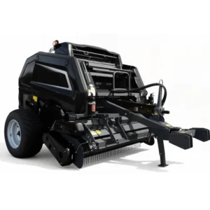
9YG-2.24D S9000
55–100 kW | φ1300×1400
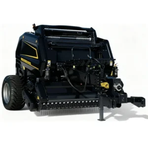
9YG-2.24D Classic
55–100 kW | Double-side chain
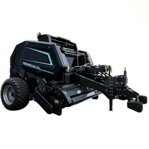
9YG-2.24D Transcend
Dual gearbox | Safety PTO shaft
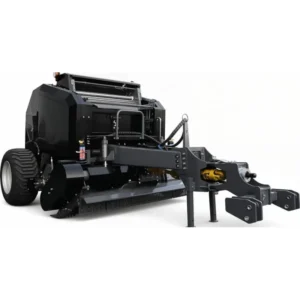
9YG-1.25
≥75 kW | Corn stalk capable
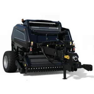
9YG-1.25A
≥75 kW | 540–1000 r/min PTO
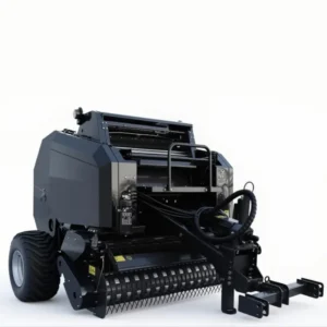
9YG-1.0
48–80 kW | Mini round baler
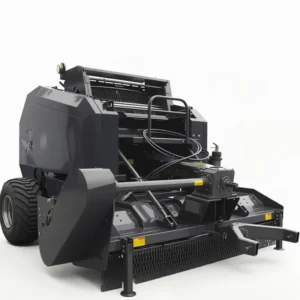
9YG-1.0C
≥69.8 kW | Hammer-claw pickup

Frequently Asked Questions
Redattore: PXY