Round Baler Technology Guide
What Is the Role of the Bale Chamber Rollers in Round Baler Performance?
A deep-dive into how compression rollers define bale density, shape consistency, and overall machine reliability — with technical detail on construction, materials, and regulatory context.
Ask any experienced operator what separates a productive round baler machine from a frustrating one, and most will eventually point to what happens inside the bale chamber. The pickup reel gathers the material, the feeder moves it inward, but the compression rollers are where the actual bale is born. These rollers — arrayed in a circular pattern around the interior of the chamber — rotate simultaneously to accept incoming crop, gradually build up rotational pressure against an expanding core, and ultimately produce the tightly wound cylindrical bale that gets wrapped and ejected.
Despite their central importance, bale chamber rollers are often overlooked in equipment discussions that tend to focus on pickup width, bale size, or PTO speed. This article addresses that gap. Whether you are evaluating a new round hay baler, troubleshooting inconsistent bale density, or simply trying to understand what the specifications mean when a manufacturer lists 18 rollers at φ222 mm, the following sections lay out the mechanical logic, the construction realities, and the operational implications of roller system design.
For a full look at available models and their roller specifications, the complete round baler product catalog is a useful reference point.

1. Action Mechanism: How Bale Chamber Rollers Actually Work
The action of the bale chamber rollers in a drum-type round baler follows a consistent mechanical logic that is worth understanding from first principles. Each roller is a steel cylinder mounted on bearings at both ends, driven either directly via chain from the machine’s main drive shaft or indirectly through the contact friction of adjacent driven rollers. As crop enters the chamber from the feeder system, the rotating rollers catch the material and impart rotational motion to it. The initial loose mass of incoming forage begins to rotate as a unit — what engineers call the bale core — and as more material is added, the core expands outward against the surrounding rollers.
The key mechanical event is that the rollers do not simply spin freely; their combined rotation creates a compressive force on the growing bale core that increases as the bale diameter expands toward the chamber wall. This is why bale density is largely a function of the final pressure between the bale surface and the roller array at maximum bale diameter. In modern machines, this pressure is monitored by a sensor system — typically a load-cell or pressure-transducer arrangement — that feeds data to a control display, allowing the operator to set target density values and receive an alert when each bale reaches that specification.
The number of rollers in the array matters for two reasons. First, more rollers mean a shorter arc length of unsupported bale surface between any two adjacent rollers, which reduces the tendency for soft spots or flat facets to form on the bale exterior. Second, a larger number of smaller contact points distributes the compression force more evenly around the circumference. The 9YG-2.24D series, for instance, uses 18 rollers each at φ222 mm diameter, arranged to cover the full interior circumference of a compression chamber 1,400 mm wide and φ1,200 mm in diameter. This geometry produces bales up to φ1,300 mm × 1,400 mm with densities ranging from 100 to 200 kg/m³ depending on crop type, moisture, and operator settings.
The rotational direction of the rollers is also worth noting. All rollers in the array turn in the same net direction relative to the bale core — their surfaces move in a direction that aids the core’s rotation rather than fighting it. If any roller were to counter-rotate due to a chain jump or bearing seizure, it would immediately create a shear zone at the bale surface and cause internal tearing, visible as a loose or stratified interior when the bale is cut open. This is one reason why chain tension maintenance and bearing condition monitoring are not optional maintenance tasks on a well-run operation.
2. Manufacturing Structure: How Rollers Are Built
A bale chamber roller is not a simple tube. The manufacturing specification for each roller balances weight, strength, surface hardness, dimensional consistency, and the geometric precision needed to maintain uniform gaps between adjacent rollers throughout the full range of bale diameters. Getting any of these factors wrong produces performance problems that are often difficult to diagnose in the field — they show up as density variation, net-wrap failure, or premature chain wear rather than as an obvious mechanical fault.
The roller shell — the outer cylindrical surface — is typically cold-rolled seamless steel tube, chosen for its consistent wall thickness and smooth external surface. Surface roughness on the roller exterior is a deliberate specification: too smooth and the roller slips against the bale surface without imparting sufficient rotational torque to the core; too rough and the roller grabs crop fibers and pulls them away from the bale surface, causing surface loss and potential wrapping around the roller shaft. Most manufacturers use a lightly knurled or serrated surface profile on the central portion of each roller, with smoother zones at the ends where the roller approaches the chamber side walls.
End caps and bearing housings are machined from cast iron or steel billet and pressed or bolted onto the roller shell ends. The bearing itself sits inside the housing; most current designs use sealed deep-groove ball bearings or cylindrical roller bearings depending on the load rating required. The chain sprocket — which drives the roller and connects it to the main drive system — is typically welded or spline-fitted to one end cap. Alignment between the sprocket and the bearing center is critical; even a small angular error accumulates into premature sprocket and chain wear over thousands of operating hours.
| Model | Roller Count | Roller Diameter | Chamber Width | Chamber Dia. | Max Bale Size | ベール密度 |
|---|---|---|---|---|---|---|
| 9YG-2.24D (S9000) | 18 (drums) | φ222 mm | 1400 mm | φ1200 mm | φ1300 × 1400 mm | 100–200 kg/m³ |
| 9YG-2.24D Classic | 18 (drums) | φ222 mm | 1400 mm | φ1200 mm | φ1300 × 1400 mm | 100–200 kg/m³ |
| 9YG-1.25 | 18 | 222 mm | 1250 mm | 1200 mm | 1200 × 1250 mm | 115–200 kg/m³ |
| 9YG-1.25A | 18 (drums) | φ222 mm | 1250 mm | φ1200 mm | φ1300 × 1250 mm | 100–200 kg/m³ |
| 9YG-1.0 | 16 (drums) | φ222 mm | 1000 mm | φ1000 mm | φ1100 × 1000 mm | 115–200 kg/m³ |
| 9YG-1.0C | 16 (drums) | φ222 mm | 1250 mm | φ1000 mm | φ1000 × 1250 mm | 115–200 kg/m³ |
One structural detail that distinguishes premium machines from entry-level alternatives is the roller surface treatment. A hard-chrome or induction-hardened surface layer on the roller shell dramatically extends wear life in abrasive crop conditions — particularly rice straw and corn stover, both of which carry silica particles that act as a fine grinding compound against any surface they contact. Machines designed for Korean paddy-region harvest conditions, where rice straw baling is routine, benefit significantly from this specification.
3. Material System: Steel Grades, Surface Treatments, and Wear Paths
The materials used in bale chamber rollers are chosen to satisfy competing demands: high tensile strength to resist bending under the load of a fully formed bale pressing outward, good surface hardness to resist abrasion, sufficient toughness to absorb impact when a hard object — a stone, a piece of wire, or a dense crop node — passes through the chamber, and dimensional stability over a wide temperature range. No single steel grade satisfies all of these requirements optimally, which is why roller design involves deliberate material layering.
The roller shell body is typically manufactured from S355 or equivalent structural steel, which provides a good balance of yield strength (minimum 355 MPa) and weldability. This grade is widely used in agricultural machinery frames and rotating components globally. For the outer working surface, a harder overlay is applied — either through surface induction hardening (bringing the surface layer to 55–60 HRC) or through thermal spray coating with tungsten carbide or chrome oxide. Induction hardening is more common on production machines because it can be applied to a pre-machined surface without distorting the dimensional tolerance of the roller, whereas thermal spray requires post-application grinding.
The bearing steel used in the roller end housings is typically 100Cr6 (equivalent to SAE 52100), the standard bearing steel for agricultural applications. This grade provides high hardness (60–66 HRC in the finished bearing race), excellent fatigue resistance under cyclic loading, and good dimensional stability. Sealed bearings in this steel with a high-temperature grease fill are the preferred specification for bale chamber rollers because they eliminate the need for external lubrication points on each individual roller — in a machine with 16 or 18 rollers, even a 10-minute per-roller greasing interval would impose an unacceptable maintenance burden.
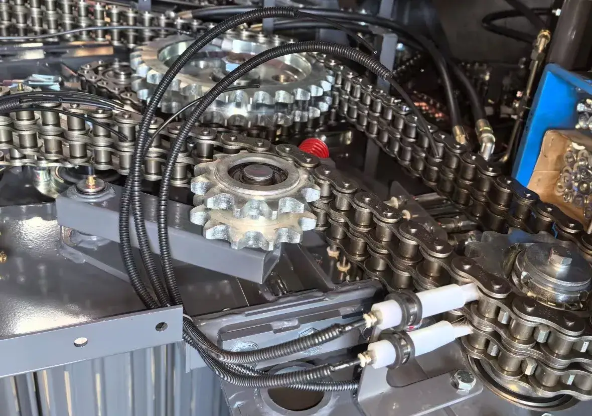
Chain and sprocket materials complete the drive system. The roller drive chains in the 9YG-2.24D S9000 rear chamber use dual-side 20A heavy-duty reinforced chains — a specification that directly reflects the elevated torque environment created by compressing dense bales. The 20A designation indicates chains with a 31.75 mm pitch and a minimum breaking load of approximately 55 kN per strand. Running dual-strand chains on the rear chamber doubles the effective load capacity and provides redundancy: if one strand develops a wear-induced fault, the second strand continues to carry the drive load while giving the operator time to reach the end of the field before shutting down.
4. Bale Density Control: How Rollers Interact With Sensor Systems
Modern round balers have moved well beyond the operator simply watching the bale diameter gauge and deciding when to stop. Sensor-based density control — standard across the 9YG series — places the measurement loop around the rollers themselves rather than around the bale exterior. As the bale grows and presses harder against the surrounding roller array, force sensors detect the increasing reaction load in the chamber frame. This load data is translated into a real-time density estimate that displays on the cab monitor and triggers an audible alert when the pre-set target is reached.
The accuracy of this density estimate depends critically on the mechanical consistency of the roller array. If rollers have worn unevenly, or if bearing preload has changed due to wear, the force distribution around the chamber shifts. The sensor may then read a density value that is systematically offset from the true average bale density. Operators who notice that bales are consistently lighter or heavier than the target despite hitting the sensor alert point should consider roller and bearing inspection as a first diagnostic step rather than assuming the sensor itself has failed.
The interaction between roller count and sensor accuracy is also worth understanding. A 16-roller chamber at φ1000 mm diameter has a smaller arc length per roller than an 18-roller chamber at φ1200 mm diameter — this means the force is distributed across more contact points per unit of bale circumference in the larger machine. The sensor system in the larger machine therefore receives a more averaged signal with less noise from individual roller variation, generally producing more consistent density readings across a production run.
Bale density figures from these machines — 100–200 kg/m³ for most 9YG series models — translate to practical bale weights that are meaningful for logistics planning. A φ1300 × 1400 mm bale at 150 kg/m³ average density weighs approximately 280–300 kg, well within the lifting capacity of a standard tractor front loader. At maximum density of 200 kg/m³, the same bale reaches roughly 370 kg, at which point bale transport equipment selection becomes a real consideration for Korean farm operations planning their seasonal hay logistics.
5. Round Baler Series — Roller System Performance Across Models
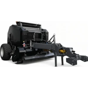
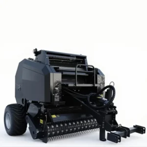
Compare roller configurations and chamber specs across the full range
6. Chain Drive, Gearbox, and the Roller Drive System
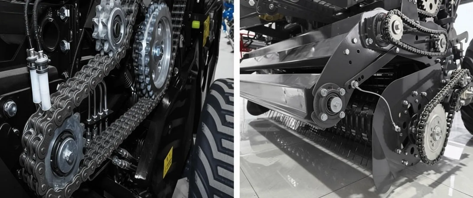
The bale chamber rollers do not operate in isolation — they are part of an integrated drive system that begins at the tractor’s PTO shaft and ends at the roller surfaces pressing against the bale. Understanding this power path helps explain both the performance ceiling of a given machine and its failure modes under demanding conditions. Power enters the baler via the PTO shaft at either 540 r/min (smaller models) or 720 r/min (full-size machines like the 9YG-2.24D series), feeds into the round baler gearbox, and is distributed from there to the pickup reel, feeder system, and bale chamber roller drive chain.
The round baler gearbox in larger machines must handle the combined load of all these systems simultaneously. Under normal operation with dry, light forage, this is a modest demand. Under peak compression with dense, wet material pushing against all 18 rollers at once, the gearbox torque can spike to several times the nominal operating value. This is precisely why specifications like the 9YG-2.24D Transcend — which cites a maximum driveshaft torque of 1000 Nm — are meaningful: they define the upper safe operating limit of the entire power path, not just the gearbox in isolation.
The chain tension in the roller drive circuit also affects roller performance in ways that are not immediately obvious. A loose chain allows the roller to momentarily accelerate or decelerate as tension fluctuates — this micro-variation in roller surface speed creates intermittent slip zones at the bale surface and can produce the irregular density distribution sometimes attributed to feeder problems. Checking and adjusting chain tension at the beginning of each day’s baling is a maintenance step that costs two minutes and can prevent an afternoon of troubleshooting.
The rear chamber in the 9YG-2.24D S9000 variant uses a dual-side sprocket transmission for the chamber rollers, which means each roller is driven from both ends simultaneously. This design eliminates the torsional twist that single-end drive systems produce under high torque — a twist that gradually misaligns the roller relative to the chamber axis and causes uneven wear on both the roller surface and the bale contact zone. Dual-end drive is a structural feature that directly affects bale quality consistency over the machine’s operating life.
7. Common Roller Faults and How to Diagnose Them
Bale chamber roller problems manifest in several distinct patterns, and learning to read these patterns significantly reduces diagnostic time. The most frequent complaint is uneven bale density — one side of the bale is noticeably denser than the other when the bale is probed or weighed. This typically points to one of three causes: uneven material distribution from the feeder (a windrow alignment issue), differential roller wear on one side of the chamber, or a failing bearing on one of the rollers in the array that causes it to drag rather than spin freely.
| Symptom | Likely Roller Cause | Diagnostic Check | Corrective Action |
|---|---|---|---|
| Bale denser on one side | Seized roller bearing on low-density side | Rotate each roller by hand, check for drag | Replace bearing or full roller assembly |
| Net wrap fails to start | Worn roller surface — low bale rotation speed | Measure roller shell diameter, compare to new spec | Replace rollers at or beyond wear limit |
| Bale has flat face (egg-shaped) | Broken or missing roller in array | Visual inspection of full roller array | Replace missing or fractured roller |
| Excessive chain noise in chamber | Chain slack from roller sprocket wear | Measure chain sag, check sprocket tooth profile | Adjust tensioner; replace chain and sprocket together |
| Bale loose in center, dense outside | Insufficient initial roller grip on bale core | Check roller surface profile; measure inter-roller gap | Resurface or replace rollers; adjust feeder speed |
A particularly useful field diagnostic is to weigh three consecutive bales from the same windrow at the same machine settings and compare. Variance of more than 8–10% between bales that are baled at the same density setting from uniform windrow material almost always points to a mechanical inconsistency in the roller array rather than a crop or operator variable. Keeping a simple log of bale weights during the season is one of the cheapest condition-monitoring tools available.
8. Roller Replacement Intervals and Lifecycle Management
How long do bale chamber rollers last? The honest answer is that it depends enormously on crop type, operating hours per season, and whether the machine is well-maintained. On a machine primarily baling dry pasture grass in relatively clean conditions, well-built rollers may run for 800–1200 operating hours before surface wear begins to noticeably affect bale quality. In abrasive crop conditions — silica-rich rice straw, sandy-soil hay, or corn stover with high stem-fragment content — that figure can drop to 400–600 hours before replacement becomes necessary.
The practical wear metric for a roller is its surface diameter. When the shell diameter has reduced by 4–6 mm from the new specification (φ222 mm in the case of the 9YG series), the inter-roller gap has increased enough to allow crop fibers to lodge between rollers and the bale surface contact area per roller has decreased, both of which degrade bale quality. Measuring roller diameter twice per season — at the start and midpoint — with a simple digital caliper gives early warning of impending replacement needs before they become in-season failures.
Bearing replacement intervals are shorter and less dependent on visible wear. Sealed bearings in agricultural environments typically perform reliably for 500–700 hours if the machine is properly stored over winter and the bearing seals are intact. At the beginning of each season, spin each roller by hand and listen for roughness or feel for dragging. Replace any bearing that has audible noise, detectable roughness, or requires more than light hand pressure to turn. The cost of a replacement bearing is a fraction of the cost of a failed bale season.
For operations in Korea’s variable seasonal climate — wet springs, dry summers, humid autumns — rollers and bearings that are thoroughly cleaned and dried before winter storage consistently last longer than those left in the machine with residual moisture and crop debris packing against the surfaces. Post-season washing with low-pressure water, drying, and a light protective oil or wax application on exposed metal surfaces adds less than an hour to seasonal storage preparation and measurably extends component life.
9. Regulatory Standards Governing Bale Chamber Design: Korea and Global Context
Agricultural machinery sold and operated in Korea falls under the framework established by the Act on the Promotion of Agricultural Mechanization (농업기계화 촉진법) and its associated enforcement regulations. Under this framework, the Rural Development Administration (RDA) and the Korea Agricultural Machinery Industry Association (KAMIA) coordinate the technical inspection and certification requirements for powered agricultural machines including round balers. Bale chamber safety — specifically, the guarding of rotating rollers to prevent operator access during operation — is a defined requirement under these regulations. Physical guards must prevent entry from any direction into the active roller zone while the machine is in motion, and must be designed to resist the ejection forces that can occur if a foreign object enters the chamber.
The gearbox and roller drive system also fall under specific requirements. Korean KS (Korean Industrial Standard) documents aligned with ISO 11684 mandate that hazardous rotating components including drive chains, sprockets, and gearbox output shafts be enclosed or guarded to a defined standard. For imported machines, the importer is responsible for verifying that the guarding meets Korean requirements, which may differ in specific dimensions or materials from the CE-marked configuration shipped from the factory.
In the European Union, round balers and their bale chamber systems are governed by Directive 2006/42/EC (Machinery Directive), now transitioning to EU Regulation 2023/1230 which entered force in June 2023. The harmonized standard EN 703:2004 (Agricultural machinery — Silage-making equipment — Safety) covers bale chamber roller guarding and specifies minimum guard geometry, maximum openings, and the requirement for interlock systems on doors or panels that provide access to the roller zone. CE marking requires full technical documentation including a description of the roller drive system, guarding measures, and residual risk assessment under these standards.
In the United States, OSHA regulations 29 CFR 1928.57 (Guarding of farm field equipment, farmstead equipment, and cotton gins) specifically require guarding on all power-transmitting components of agricultural machinery. The ASABE Standard S318 (Safety for agricultural field equipment) provides engineering detail on guard design for rotating components in field machines. While US requirements are not directly enforceable in Korea, major manufacturers design to the most demanding applicable standard across their global markets and then document compliance with regional variants, which means US-market specifications often represent a useful baseline for evaluating any machine regardless of where it is to be operated.
Japan’s Agricultural Machinery Act and associated JAMAS standards govern machinery sold in Japan, with specific provisions for bale chamber safety that are worth referencing by Korean importers given the similarity of agricultural practice and field conditions between the two countries. The Japan Agricultural Standards (JAS) framework for hay quality certification also indirectly affects round baler bale chamber requirements by specifying minimum bale density standards for certified hay — which in turn drives the engineering requirements for roller compression capability in machines destined for markets where JAS-certified hay commands a premium.
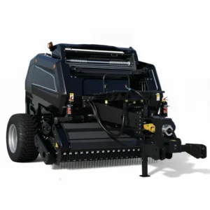
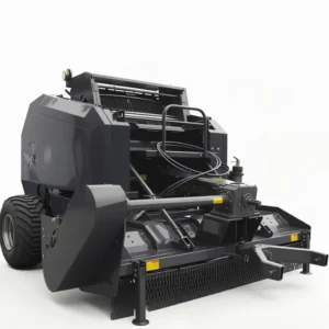
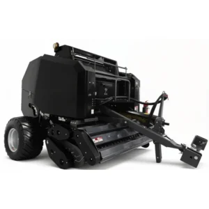
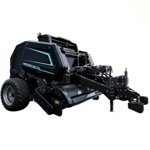
10. Additional Round Baler Models With Roller Configuration Details
11. Drum Rollers vs Belt Systems: Understanding the Design Choice
The bale chamber design discussion inevitably arrives at the comparison between drum-roller systems and belt-based systems. Both are widely used in the global round baler market — belt-type machines are common in the product lines of Western brands, while drum-roller systems predominate in Asian-manufactured machines including the entire 9YG series. Each design has genuine advantages and genuine limitations that are worth understanding clearly rather than dismissing one in favor of the other.
Belt-type bale chambers use one to three continuous rubber belts, typically 200–300 mm wide, supported and driven by internal rollers. The bale forms inside a loop of moving belt. The advantage of the belt system is that it provides continuous contact across a larger arc of the bale surface, which produces very consistent density distribution without the inter-roller gaps that exist in a drum system. Belt systems also tend to handle short, chopped material (like silage) more cleanly because there is no gap for short fibers to escape through. The disadvantage is maintenance cost: belts stretch, crack, and require periodic replacement, and a belt failure mid-field can be difficult to manage compared to a roller issue.
Drum-roller systems, as used throughout the 9YG series, have higher initial mechanical durability in abrasive crop conditions — steel rollers resist silica and grit abrasion far better than rubber belts — and the drive system is mechanically straightforward, with fewer failure modes than a multi-belt arrangement. Maintenance is individual-roller based: a worn bearing or damaged roller can be replaced as a single component rather than requiring a full belt replacement. For operators baling rice straw or corn stover in Asian field conditions, these durability characteristics are meaningful.
The practical performance gap between the two systems in terms of finished bale quality has narrowed considerably as drum-roller engineering has improved. The 18-roller arrays in the 9YG-2.24D series, with their φ222 mm diameter rollers providing close inter-roller spacing around a φ1200 mm chamber, produce bales with density consistency that compares favorably with belt machines in independent field trials on similar crop types.
Frequently Asked Questions
編集者: PXY